Continue to Site

Welcome to our site!

Electro Tech is an online community (with over 170,000 members) who enjoy talking about and building electronic circuits, projects and gadgets. To participate you need to register. Registration is free. Click here to register now.

  • Welcome to our site! Electro Tech is an online community (with over 170,000 members) who enjoy talking about and building electronic circuits, projects and gadgets. To participate you need to register. Registration is free. Click here to register now.

LM317 voltage regulator!

Status
Not open for further replies.

drkidd22

Member
I'm trying to use an LM317 as a voltage regulator to drive a fan.
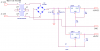
There is a transformer driving 220VAC to 24VAC on secondary coils when in series.
This goes intro the bridge rectifier and from the rectifier to the LM317.

Fan draws 120mA @ 24V. (2.4W)
My R1 is 220 Ohm (1/4W)
and R2 3900 Ohm .

According to the data sheet I should be getting ~22+ VDC, but I'm only getting like 18VDC.

shouldn't it be (R1/R2)*1.25 to get Vout?
Maybe because my Vin is same as I want for Vout is giving me a problem?
 
Last edited:
Hi there,

A 24vac wave has a lower average value, and that is what you are measuring, and that is getting to the input of the LM317 so the output could measure even lower.

You should add at least 220uf capacitance across the bridge rectifier and that will improve the average value if you really think you need the full 22v output. The voltage rating should be at least 35vdc but 50vdc preferred.
Otherwise, you might be able to connect directly to the output of the bridge rectifier if you dont expect any extreme dips or surges in voltage (provided you have NO capacitor across the bridge). It depends though if the fan can take the higher peak voltage, which unfortunately it may not be able to handle.

The LM317 output voltage is Vout=1.25*(1+R2/R1)+50e-6*R2 which comes out to about 23.6v for your setup, but that figure is subject to resistor tolerances and other slight variations.

R2=3.3k will give you about 20v output, so 3.6k should give you around 22v output if that's what you want.
 
Last edited:
You did not post your schematic so we are just guessing that you forgot to use a filter capacitor after the bridge rectifier. Then the input to the LM317 was jumping up and down from 0V to 32V and the average voltage at its output was a fluctuating 18VDC.
 
I don't have a cap in the 200uF range, so I installed two 150uF 35V caps right after the rectifier in parallel to get 300uF, what I need is 24VDC not 22VDC out the LM317.

Now my output from the LM317 is 35VDC, way over.

This is the chem as I have the LM317 right now.
 

Attachments

  • LM317 Fan.JPG
    LM317 Fan.JPG
    26.2 KB · Views: 351
Several issues:

1. Without a load, you must have at least 10 ma being pulled from the LM317. This is the reason the resistor shown for feedback is 120Ω, it makes the regulator meet the minimum requirements. If you have a full load you can get by with less, but the moment you try to use the regulator without its load you've run into this specification. I would go with 120Ω for R1 and 2.2KΩ for R2.

2. A LM317 requires a capacitor on the input and the output. You've meet the input specs, but you need around 0.1µF on the output. A 0.1µF is also recommended on the input side. This prevents the LM317 from oscillating, and is also in the datasheet.

3. Your design doesn't have this problem, but you need to know the LM317T needs around 3V above the regulating voltage to work.
 
Last edited:
I got it figure out. I had a wiring mistake. Voltage is at 23.4 volts and stable with above circuit.

So my question now is with the .1uF cap that is mentioned in data sheet for input voltage to regulator, should I just place one in parallel with the two that are already in?
Wouldn't the two caps that I have make up for .1uF making it un-required?
 
Last edited:
The two 150uf filter capacitors are electrolytic that do not filter high frequencies well. They filter the 100Hz or 120Hz from the full-wave rectifier very well. The 0.1uF capacitor is a good filter for high frequencies and stops the LM317 from oscillating at a high frequency.
 
Hello there,

You also need to check the voltage level across the two 150uf caps, as i see you did use 35v rated devices and that's a little close to the actual voltage you might measure there, but at high line the voltage could go above 35v that's why i was saying that 50v devices would be preferred. That's quite important too or the caps could become damaged. Do you have any 50v caps around?

The caps on the rectifier are determined by calculating the min voltage of the ripple waveform with full load current flowing. The idea is to have enough capacitance so that for any low line condition the rectifier still puts out enough voltage to run the load properly. For example, if the load requires at least 12v (including regulator overhead) and 100uf allows the voltage to dip below 12v (say 11v) then we need to add more capacitance. If we add 50uf in parallel with the 100uf and that keeps the voltage above 12vdc (at low line) then we're good to go, except we might also want to factor in a little capacitor aging in which case we can make the total capacitance 150 percent higher, which would work out to about 220uf for this example.
Most people do a simulation to determine if the capacitance is acceptable, but i have a special program developed for these rectifier circuits that is much faster than a simulation if you would like to try it. With a decent computer the simulations are not that slow anymore though anyway, so if you have a circuit simulator you can try that first if you like. You should realize though that in the real world there is always some input series resistance presented by the windings on the transformer, and that helps with the filtering too although it does lower the output voltage a little more. You can estimate this resistance by measuring the input and output characteristics of the transformer but im not sure if you want to be bothered by those details, especially since you have test equipment you can use to measure the real world performance once you get it up and running.


The other caps (0.1uf) are taken from what the manufacturer recommends, although you have the right idea already: check it with a scope and look for oscillations. You need to check at both low line and at high line too however, which you can take to be plus or minus 15 percent of the nominal line voltage. You should also check your max dc voltage level across the caps at high line too as i was saying above. If you dont have a variac on hand to raise and lower the input line voltage, you can estimate by multiplying the voltage measured across the caps at nominal line by 1.15 for high line and 0.85 for low line. You dont want the voltage going above this level or below the level needed for the LM317 to regulate into your required load (about 2.5v above output).
 
Last edited:
The 0.1uf at terminal of LM317 is for high frequency filtering. It assumes you have a good filter DC from supply. You probably have 34-35 vdc after putting on the 300 uf filter. You are pushing the voltage rating on electrolytics at 35 vdc. You should go to 50 vdc rated caps.

You need a little heat sink on LM317. You are dissipating about 1.2 watts on LM317.
 
Last edited:
Ok, check the circuit that I have now.
I really want to make something really good and understand it.
It works fine as it is, but just wanted to know if it could be made better or if I'm missing something.

I have built this on a breadboard already. The most critical is the 5V, since it's going to be driving a micro-controller.
 

Attachments

  • 24v_5V LM317.PNG
    24v_5V LM317.PNG
    37.5 KB · Views: 247
Last edited:
Hi,

Did you check the voltage across the 150uf caps and make sure it doesnt go too high at high line yet?
 
Yes, It's ~33VDC under load (fan on), too close to the cap limit.
Checked with no load and the voltage across caps is ~37V, no good.
I found a 220uF 63V Cap, I will replace those two with one of the 220uF and let you know what the voltage across it is. Or should I use a bigger one, like 330uF 63V?

I still don't understand much of why the need of this cap, is it just to keep from having the regulator to receive an oscillating signal? and why does the voltage go up after the cap is added?

Do I have to use C=IT/E to determine the capacitor size?
Thanks
 
Last edited:
The output from the bridge rectifier is humps of voltage at 100Hz or 120Hz that go from 0V to the peak of the 24VAC which is +34V.
The 300uF capacitor smooths the humps and powers your circuit between the humps and it charges to about 1.5V less than the peak voltage.
The 24VAC transformer has an output voltage that is higher when its load current is not at its max current rating.

The regulator IC does not regulate anymore when its input voltage drops to less than 1.5V to 2.0V more than its output voltage and it will reproduce the voltage humps (actually it will produce voltage drops) at its output if the input voltage drops too low beween humps from the filter capacitor.
 
Status
Not open for further replies.

Latest threads

New Articles From Microcontroller Tips

Back
Top