Roff
Well-Known Member
Regarding your comment on Carl the curmudgeon's idea:
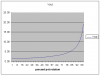
The problem I have with this method is that Vout is a very nonlinear function of pot rotation. Attached is a plot that I did on Excel, using Carl's example. An LTspice simulation gave a virtually identical curve.
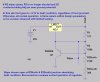
Keep in mind that only the wiper is connected to the ADJ pin, so if the wiper opens, ADJ is grounded through 10k (or whatever). Therefore the output voltage will fall to a low value, somewhat above Vref.You might want to draw that out and compare it with the standard configuration, and then run the numbers. From your discription, if I am interpreting it correctly, the output could not come down to that range. R2's value needs to be pulled down to drop the voltage in case of a wiper fault. Its that darn common current again. R1 must go across the Adj and Out pins.
The problem I have with this method is that Vout is a very nonlinear function of pot rotation. Attached is a plot that I did on Excel, using Carl's example. An LTspice simulation gave a virtually identical curve.
Attachments
Last edited:
")
")