confounded
New Member
Hi, i'm not sure if part of my project is working correctly.
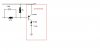
Its from a magazine, and on their diagram output at pin 7 of the lm311 a rectangular waveform is shown.
The inverting input is aprox 100khz triange wave and the non inverting input is aprox 5V dc. (see pics) (i've used 10x probe so voltage on pics are 1/10 voltage)
(The noninverting input will carry an audio signal later)
The output will be a pwm signal.
However on both my project and a circuit i've built on a breadboard to try and work out what ive done wrong i get a non rectangular output at pin 7. As shown on pic but its not a clean trigger, i just captured a split second image, its actually jumping everywhere
Is this the output correct? If not what do you think i've done wrong?


") so is the waveform im getting expected with the components in place or do you think i have misconnected them?
so is the waveform im getting expected with the components in place or do you think i have misconnected them?


