Continue to Site

Welcome to our site!

Electro Tech is an online community (with over 170,000 members) who enjoy talking about and building electronic circuits, projects and gadgets. To participate you need to register. Registration is free. Click here to register now.

  • Welcome to our site! Electro Tech is an online community (with over 170,000 members) who enjoy talking about and building electronic circuits, projects and gadgets. To participate you need to register. Registration is free. Click here to register now.

LM311 need help

Status
Not open for further replies.

Suraj143

Active Member
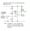
I’m doing a small project which requires to compare two voltages. Here I used LM311 comparator IC.

The theory says when the non inverting (+) input is higher than the inverting (-) input the output becomes on.

When the non inverting (+) input is lower than the inverting (-) input the output becomes off. That is 0V.

My supply voltage is 5V

Q1) In the output pin is it coming a 5V or another value like 1V, 2V etc….can I directly give an input to a CMOS IC?

Q2) I have 2.1V in non inverting input (+) pin. & I have 2V in invert (-) pin. Will the output becomes 5V?

Q3) what’s the gap between those two pins to give an output? What is the minimum voltage different between those two pins to give an output?
 
1) the output voltage will be a function of how much current the output must conduct, which is of course dependent on the load resistance. If the load resistance is extremely high (which would be the case if you are driving CMOS logic) then the output will be 4.9V when high and 0.1 volts when low. So it would be compatible with the CMOS. To determine the actual output voltage, refer to the LM311 data sheet graph called "Output Saturation Voltage". This graph shows how much voltage is dropped at the output (compared to either 0V if output is low or Vsupply if output is high) inside the LM311 with different amounts of output current.
2) The output will become very close to 5V (perhaps 4.9V).
3) see the LM311 data sheet, a graph for the LM311 called "transfer function". It shows the output vs input and shows that the difference between input and output should be greater than 0.2mV to saturate the output correctly. However, this value is much smaller than the offset voltage specification, so I will assume that this is achieved after applying offset correction as shown in the Typical Applications diagram called Offset Balancing. Without correcting the offset, the difference may have to be as much as 7.7 mV.
 
Thankx radioron for your quick response.

I asked this question because I want to turn a led bulb on when the non inverting input is more than the inverting input.

I adjust the non inverting pin to 1.4v. To check whether it’s working correctly I gave a 1.5v cells + terminal to inverting input (-) pin & the cells (-) terminal to GND.
For the output I connected led directly to the positive supply.

In this case all the time the led lights up. Even the cell voltage is more than I adjusted.
1.5V > than 1.4V
How can I turn on or off the led after reaching 1.5V or 1.41V.in the inverting pin?

Thankx a lot
 
If you are connecting the LED directly between the output and the positive supply you must include a series resistor (about 270 ohms) otherwise you may cause damage to either the comparator or LED (or both).
 
Suraj143 said:
For the output I connected led directly to the positive supply.

Thankx a lot

Which means you are sinking current from the positive rail, since the output of the comparator is negative (1.5 v inverted compared to a 1.4 positive reference).

Also, use a resistor to limit current to the LED
 
If you want to turn on an LED which is connected from +5V (through a resistor) to the pin 7 output, you must drive the output low, which means the inverting input must be higher than the noninverting input. If you also want good logic levels, you need to connect a resistor (10k will work) directly from pin 7 to +5V, in parallel with the LED/resistor combination.
 
Last edited:
Thankx a lot guys.
I must use that resistor in series with the LED & try.All the time I checked that without resitor.
When the battery voltage increased more than the adjusted value on noninverting input which means 1.5V > 1.4V then the LED should lights up.

I will post the full diagram after checking what I'm doing.Its easy to refer otherwise.....

Thanx Ron......Thankx Allvol.......Thankx dch222
 
If you do not already know what value resistor to use then consult the spec sheet of the LED to get its voltage and current ratings. If you are using a standard diffused red LED then a 330 ohm up to a 500 will be what you need. Sometimes they will even light up with a 1k ohm.

R = (5V - Vf) / If
 
Hi guys, thanks for the replies…

**broken link removed**

The problem was the resistor in series with the LED. After I added the resistor it worked fine.

I kept pin 3 = 1.4V & checked with a 1.5V cell.
LED turned off when PIN3 < PIN2 (1.5V>1.4V) output goes high.

When the value gap comes like this Pin3 = 1.4V & Pin2 = 1.41V the LED started to blink like pulses. It cannot recognize suddenly.

Now I need to give a clean pulse to a logic gate. 5V or 0V.when the battery voltage comes more than the adjusted inverting pin must give a pulse.

If I add a resistor to the positive supply & the output pin it will be harm to the LED.

So how can I give a pulse to another logic IC? Also must show the LED as well.
 
Now I need to give a clean pulse to a logic gate. 5V or 0V.when the battery voltage comes more than the adjusted inverting pin must give a pulse.
Depending on the logic IC type, you may just be able to connect it to pin 7 of the LM311 in the circuit you posted.
When the value gap comes like this Pin3 = 1.4V & Pin2 = 1.41V the LED started to blink like pulses. It cannot recognize suddenly.
You need to add some hysteresis as noted below:
 

Attachments

  • lm311.GIF
    lm311.GIF
    6 KB · Views: 2,667
Last edited:
Suraj143 said:
So how can I give a pulse to another logic IC? Also must show the LED as well.

I suggest you go to this very complete website for further information: **broken link removed**
 
Thanks kchriste your hysteresis method worked well. Now it won’t give any pulses when the input voltage gap becomes very small.

When the output pin becomes HIGH its showing 5V.

1. But when the output pin becomes LOW its showing 2V.not 0V.So when I take an out from here to another IC will it be a problem? Also I need to invert the logic level.

2. Also without the battery if I adjusted the reference voltage to 1.4V, after connecting the battery its dropping down to 1.28 something like that is it real..?
 
Your schematic is missing some wires. The output pin 7 of the LM311 will go close to ground as a low if pin 1 is connected to ground.
 
But when the output pin becomes LOW its showing 2V.not 0V.
Make sure pin 1 of the LM311 is connected to ground as noted by AudioGuru... The output should be less than 0.7V when low, for the load you have in the schematic.

Also I need to invert the logic level.
You could use a transistor, inverter or a different logic gate.
Also without the battery if I adjusted the reference voltage to 1.4V, after connecting the battery its dropping down to 1.28 something like that is it real..?
I assume you are talking about the voltage in pin3 of the LM311.... Check the 5V supply, I suspect it is dropping to 4.6V or so when you connect the battery.
 
Suraj143 said:
2. Also without the battery if I adjusted the reference voltage to 1.4V, after connecting the battery its dropping down to 1.28 something like that is it real..?

The battery (cell) as shown in your and KChristie's diagram is in the wrong place. See the attachment below.

You want the output low, in order to turn on the PNP transistor.

Also, I refer you once again to **broken link removed**
which explains all.


Edited to remove speculative phrase.
 

Attachments

  • LM311.JPG
    LM311.JPG
    22.8 KB · Views: 3,181
Last edited:
AllVol said:
The battery (cell) as shown in your and KChristie's diagram is in the wrong place. See the attachment below.

You want the output low, in order to turn on the PNP transistor.

Also, I refer you once again to **broken link removed**
which explains all.


Edited to remove speculative phrase.
I looked at the schematic and concluded it was a battery charger, in which case the battery was in the correct location.
 
He originally posted:

Suraj143 said:
I asked this question because I want to turn a led bulb on when the non inverting input is more than the inverting input.

I adjust the non inverting pin to 1.4v. To check whether it’s working correctly I gave a 1.5v cells + terminal to inverting input (-) pin & the cells (-) terminal to GND.
For the output I connected led directly to the positive supply.


Thankx a lot

He originally used a 1.5V cell to check the comparator's operation, if I am not mistaken. I missed the part where it became a battery charger.
 
AllVol said:
He originally posted:


He originally used a 1.5V cell to check the comparator's operation, if I am not mistaken. I missed the part where it became a battery charger.
He never said it was a battery charger. He also never said his purpose was
to check the comparator's operation.
He said he was
doing a small project which requires to compare two voltages.
I looked at the schematic and concluded that "the small project" was a battery charger. As you can see, the PNP is a current source which charges the battery until the battery voltage reaches the voltage set by the pot. Then the current source turns off.
Obviously, I could be wrong. I don't believe he ever said what the logic level output was going to be used for.
 
Thanks every body who involved to this thread.
A little about my circuit,
Earlier I planned to use this comparator as a battery charger. When the batteries charged to a certain level the output goes high & turn off the transistor.

I need to give the LM311 output to the CMOS because I need to connect an alarm to the circuit. When the battery is fully charged it’s giving & alarm.

Even though I added hysteresis to the circuit still it’s giving pulses when the input voltage gap becomes closer.

Finally I planned to charge the batteries with LM317 constant current.

My final question in this thread is I want to connect this LM311 as a voltage detector in the LM317 circuit below.

**broken link removed**

When it’s charging if its not exceed the reference voltage (1.4 V) then the out put will be high turning the red LED.
When it’s full charged & exceeding the reference voltage (1.4 V) then the out put will be low turning the green LED.

Is this method is good to detect the battery is charged or not? Any modifications?

Thanks a lot….
 
Suraj143 said:
Is this method is good to detect the battery is charged or not? Any modifications?

No, it's not any good - assuming you're charging NiCd or NiMh?, to detect full charge you need to detect a DROP in the terminal voltage - once the battery is fully charged the voltage drops off and the battery gets hotter.
 
Status
Not open for further replies.

Latest threads

New Articles From Microcontroller Tips

Back
Top