Continue to Site

Welcome to our site!

Electro Tech is an online community (with over 170,000 members) who enjoy talking about and building electronic circuits, projects and gadgets. To participate you need to register. Registration is free. Click here to register now.

  • Welcome to our site! Electro Tech is an online community (with over 170,000 members) who enjoy talking about and building electronic circuits, projects and gadgets. To participate you need to register. Registration is free. Click here to register now.

LM2577 Voltage converter problems...

Status
Not open for further replies.

formant84

New Member
Hi,

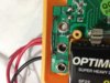
I ordered one of the LM2577 PCBs you can get from ebay a while ago that have the full circuit wired up and ready to go. I used it when breadboarding a design that requires me to get 12v from a 5v USB port. when I came to design my own board I incorporated the circuit from **broken link removed** (which is exactly the same as the circuit I got from ebay) along with the stuff i designed myself to keep everything on the one board.

I had the boards manufactured, and have assembled the power regulation circuitry. itt all seems to be functioning fine, I can get the 12v I need. The only thing that concerns me is that when I measure the input voltage (which is coming from a 5v USB port) it's coming up as 3v!

This doesn't happen with the board I bought on ebay, so I'm wondering what the problem is. The rest of my circuit mainly consists of an ATMEGA32U4 microcontroller and some other bits, which should work okay on 3v, but I'd like to find out what's actually going on before I irreversibly solder this relatively expensive SMD micro to the board and risk frying the whole setup!

So... Does anyone have any ideas on what could be causing the circuit to behave in this way? any suggestions would be appreciated as i'm drawing a total blank!

Thanks in advance,

John.
 
Wild ideas off the top of my head...

The circuit which you built is drawing more current from the USB supply causing the voltage sag.

There is a high resisitance connection between your new board and the USB.

There is high frequency noise on your board (due to poor supply decoupling) which is messing with the meter you are using to measure the voltage.

JimB
 
I agree with JimB that your board is drawing more power.
I think it might be the inductor. What inductor did you use?
Part number, inductance, current, saturation point, any information you can find on both inductors.
 
Well I originally had a weedy resistor type inductor in there which wasn't up to the task, but I've replaced that with a B82111Ec25 Epcos axial leaded inductor. It's rated for 1A and has a resonant frequency of 55mhz. The inductor on the board from eBay I'm less sure about. It's one of the square black SMD variety approximately 1cm in diameter.

Both are 100uh
 
How much current are you trying to draw at 12V? If excessive, the USB port might not provide enough input current without negotiation. Perhaps it drops the volts to protect itself?
 
Do you have a cap across the 5v, if so is it a low esr type, if not the peak current which is about double the average will take effect on the supply impedance rather than the average and cause a larger v drop.
 
I think your inductor is saturation. You have a 1A inductor but the IC can easily pull 3A.
By looking at the data sheet examples closely I see they are using 3A inductors.
Also the resistance of your inductor is 10X that in one of the examples.
 

Attachments

  • b82111e.pdf
    282.5 KB · Views: 263
This is great input guys I appreciate it!

I don't think my circuit should be drawing too much current. As I haven't added the rest of the components yet I literally just have a circuit matching the one in the schematic I linked. When I hook up the board I bought in eBay to the same USB power it works fine, so it must be either the caps or the inductor.

My caps aren't low ESR just standard, so that could be a factor but I'm definitely leaning more towards the inductor being the main issue. This is the first thing I've built that requires an inductor so I know virtually nothing about them! I'll check the data sheet and try to find a better match. I'll let you know when I've tried the replacement out and see how it goes.

Thanks for all the advice!
John
 
At the risk of stating the obvious, why don't you measure how much current is being drawn from the USB supply?
(For both circuit boards).

JimB
 
Its a rather basic test however if the inductor is saturating it'll probably be getting warm.
If you have a 'scope you could put a 0.1 ohm resistance in series with the 5v and monitor the current, not only would this tell you peak and average current it'd also show you if the inductance is saturating or not.
 
Yeah it's getting warm alright, the 2577 is getting pretty hot too!

I think my multimeter has gone faulty, whatever current it's pulling is more than 200ma, but when I switch to the 10A port and setting it only registers 0.01!
 
Sounds like the core is saturating then, if so you need a core that can carry a higher dc current.
I use a simple test jig to measure core saturation, if you do this often you should make one, but it does need a 'scope.

This is an interesting site, the current in an inductor suddenly (on typical smpsu cores, some like iron powder cores have 'softer' saturation) changes to a much steeper curve at the point of saturation, basically the inductor changes into a piece of wire at that point.

http://elm-chan.org/works/lchk/report.html
 
Last edited:
No even better than that! I just opened it up and checked inside, an I being crazy or is there a big metal bar connecting the 10A socket directly to COM???
 

Attachments

  • image.jpg
    image.jpg
    1.8 MB · Views: 206
Same would probably happen on a 100 quid meter, use the 10a setting to start with if your not sure.
Replacement fuses are available, though a semiconductor fuse might cost more than a cheap meter.

The metal bar you mention is a shunt, a very very low value resistor, the 5a range will use this, a voltage is dropped across it (ohms law) which the meter measures and displays as amps.
 
I have a scope, but I don't plan to work with inductors a lot, I just really need to nail this circuit! So using the wrong inductor can cause the circuit to pull too much current? Correct?

The pre-built circuit must be using less than 500ma to work fine from USB even with the rest of my circuit wired up because I had it all bread boarded at one point.

So if I can find an inductor that will handle at least 500ma, with a resistance of 0.03ohms, should that do the trick? Are there other variables that are important? Does resonant frequency matter? Inductors seem to have an annoyingly wide set of characteristics and variables!!
 
Ahh right I had an inkling I was making myself look stupid then lol! Well the visible standard looking fuse which I assume is the high current one isn't blown :-/
 
The peak current of a switcher is approx (wait for it) twice the average, so your inductor needs to handle double the input current min, preferable 3x to be safe, if its a one off circuit then go for 3x the max of the 2577 as mentioned 3amps.
Because all the functions are in the chip there isnt a lot to worry about, the only other thing you could do is to limit the circuit max current it can draw from the usb port, but I'd worry about that if and when the problem occurs.

Looking at the photo of your meter I'd say you had an accident when you opened it, where its says 'com' and 'rx' on the bottom of the board near the input sockets there looks to be some screwdriver damage, and there are a pair of surface mount miniature resistors that look like they ahve been ripped off the pcb.
You might get away with soldering them back on the board, then you can look at what actually is wrong.
Or if it cost a few quid call it a lesson learned and buy another, dont worry about looking daft, even the experienced among us do, just that only a few will admit it.

Edit if you put a 0.1 ohm resistor in series with the inductor then put you =r 'scope across the resistor you'll be able to view the current through the inductor, sort of using your circuit as the test bed, be carefull though the 'scope ground might be earthed and so too the ground of the usb port, things might not agree.
 
Last edited:
No accident, multimeter is fine just shoddily made. I thought maybe the problem was that no load was attached to the 12v output so I re-tested with a small bulb attached to the outputs thinking this will give a good idea of current draw once it has the other stuff attached.

Surprisingly the eBay board draws 400ma in this setup and my one only 300
 
Status
Not open for further replies.

Latest threads

Back
Top