Continue to Site

Welcome to our site!

Electro Tech is an online community (with over 170,000 members) who enjoy talking about and building electronic circuits, projects and gadgets. To participate you need to register. Registration is free. Click here to register now.

  • Welcome to our site! Electro Tech is an online community (with over 170,000 members) who enjoy talking about and building electronic circuits, projects and gadgets. To participate you need to register. Registration is free. Click here to register now.

LM2576T 5v regulator circuit

Status
Not open for further replies.

lloydi12345

Member
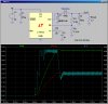
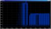
Hi again ETO. I am using LM2576T for regulating 32VDC to 5VDC. Everything in the datasheet was followed. I was able to produce 5V/0.455A with 2ohms resistor as load. 5V was read from a multimeter while 0.455A was read from my bench power supply alongside with 32V. Datasheet tells me that I could go as far as 3A. How can I achieve this setting? I think one fault here is the inductor because I am hearing a lot of humming noise from it.

Here's the link where I purchased the inductor: https://export.rsdelivers.com/produ...elc16b-radial-inductor-100uh-26a/6755545.aspx

It said that it could withstand 2.6A but it can't even pull more than an amp from the regulator.

Any feedback would be much appreciated. Thanks.
 
Hello lloydi,

I assume that the 0.455 Amps is on the INPUT side of the regulator as that is what your power supply read.

If you have a 2 ohm load at 5 volts then that is 2.5 amps which is getting close to 3 amps. To get 3 amps you need a smaller load resistor, like 1.667 ohms, or just connect another 10 ohm resistor to the output and that will draw the additional 0.5 amps.

I think they suggest a diode that is somewhat higher rated than the actual output current, like 4 amps instead of 3 amps. This might be because of the wave shape which is assumed to be triangular and that means it has a higher RMS value even when the average is around 3 amps.

I've used 3 amp Schottky diodes myself for lower current outputs like 1 amp.
 
You are forgetting that to get 3Adc at the load, the peak current through the inductor could be up to ~6A. It is the peak current that determines which inductor you need to buy. The buzzing/heating of the inductor you are using now is likely caused by core saturation because you are exceeding the inductor's 2.6A peak rating.

Here is a sim of a similar LTC step-down converter. I put in your voltage, current, and inductor values. Note that just to get the converter started, the peak current in the inductor is over 6A.

The diode current is shown in the second attachment.
 

Attachments

  • 1074.jpg
    1074.jpg
    296.2 KB · Views: 206
  • 1074d.jpg
    1074d.jpg
    199 KB · Views: 200
Last edited:
I built a nifty and simple little jig for testing when inductors saturate, I'll find the link for it if you like.
I found manufacturers ratings to be on the optimistic side.
 
Here is the link for Dekker: https://www.dos4ever.com/flyback/flyback.html#ind2

Here is my version:inductor test bench.png

I am still getting used to Win 7 and there are many differences from Win XP Pro. I dearly miss Windows Explorer as a desktop icon. I apologize for screw ups.

To say the least, it was both fun and educational to experiment with various inductors (mostly toroids) to see the effects of core saturation. I even talked CoilCraft into selling me a calibrated coil to play with.

John
 
Last edited:
jpanhalt,

With Windows 7 Click on the "start" orb, then Accessories, Then Right click on Windows Explorer, If you then drag to your desktop, release "right click" in the box that appears select "create shortcut here". you will then have the shortcut on your desktop.

O.P. sorry for off topic post. :p
 
Hello lloydi,

I assume that the 0.455 Amps is on the INPUT side of the regulator as that is what your power supply read.

If you have a 2 ohm load at 5 volts then that is 2.5 amps which is getting close to 3 amps. To get 3 amps you need a smaller load resistor, like 1.667 ohms, or just connect another 10 ohm resistor to the output and that will draw the additional 0.5 amps.

I think they suggest a diode that is somewhat higher rated than the actual output current, like 4 amps instead of 3 amps. This might be because of the wave shape which is assumed to be triangular and that means it has a higher RMS value even when the average is around 3 amps.

I've used 3 amp Schottky diodes myself for lower current outputs like 1 amp.

I forgot that the input current was different from the current load. Thanks!

You are forgetting that to get 3Adc at the load, the peak current through the inductor could be up to ~6A. It is the peak current that determines which inductor you need to buy. The buzzing/heating of the inductor you are using now is likely caused by core saturation because you are exceeding the inductor's 2.6A peak rating.

Here is a sim of a similar LTC step-down converter. I put in your voltage, current, and inductor values. Note that just to get the converter started, the peak current in the inductor is over 6A.

The diode current is shown in the second attachment.


I measured the current. 5.06V / 2.2Ohms = 2.3A.

2.3A at the I/load (+probe of multimeter to Capacitor output and -probe of multimeter to the resistor's pin while the other pin of resistor is on the ground) and I/inductor 1.7A (+probe of multimeter to output of LM2576 and -probe of multimeter to the pin of inductor).

Why is the current at the load higher than the current from the inductor?

I built a nifty and simple little jig for testing when inductors saturate, I'll find the link for it if you like.
I found manufacturers ratings to be on the optimistic side.

Here is the link for Dekker: https://www.dos4ever.com/flyback/flyback.html#ind2

Here is my version:View attachment 75509

I am still getting used to Win 7 and there are many differences from Win XP Pro. I dearly miss Windows Explorer as a desktop icon. I apologize for screw ups.

To say the least, it was both fun and educational to experiment with various inductors (mostly toroids) to see the effects of core saturation. I even talked CoilCraft into selling me a calibrated coil to play with.

John

I think that link would be really helpful and yes those inductor testers are really good idea to know their maximum capacity.


---------------------
Thanks a lot for your replies :)
 
...
Why is the current at the load higher than the current from the inductor?...

What kind of multimeter are you using? Does it do True RMS, or is it a cheapie?

The waveforms in the inductor are so complex that most meters are confused... The current in the load resistor is almost pure DC, so likely you can believe your meter there...

Remember that it is the current peaks that cause saturation in the inductor; the best you can expect your meter to tell you is the "average" current.

I am using Fluke's Multimeter specifically this one. https://www.tequipment.net/FlukeDigital73Multimeter.html

I am still clueless about the inductor current reading -_-
 
I agree with the comments on measuring the inductor current, a fluke 73 probably isnt going to do that well, most meters like this use charge balancing conversion techniques and are not designed to measure high frequency or complex waveforms, the meter is more designed for people like me finding faults on machinery, there are some that will do high freq's I had a B&K that was superb till I ran over it.

Your better using a 'scope and look at the current accross a load resistor, like the 0.1 ohm in the test jig I linked you to.

The test jig can also be expanded to get an idea of switching losses, however you need to get to that point first.
 
Last edited:
I agree with the comments on measuring the inductor current, a fluke 73 probably isnt going to do that well, most meters like this use charge balancing conversion techniques and are not designed to measure high frequency or complex waveforms, the meter is more designed for people like me finding faults on machinery, there are some that will do high freq's I had a B&K that was superb till I ran over it.

Your better using a 'scope and look at the current accross a load resistor, like the 0.1 ohm in the test jig I linked you to.

The test jig can also be expanded to get an idea of switching losses, however you need to get to that point first.

Okay, I'll just use the oscilloscope then. I have another question. What will happen if I use a diode in a smaller package than the one I am using right now? I am talking about 1n5822 which has thick pins and I am planning to replace it with 1n5822 also but with thinner pins like 1/2W resistors and it might be rated 1A. What will happen?
 
I'm confused now.
Sometimes different manufacurers make the same part with different diameter leads, is this what your saying.
If you use a 1a diode at 3 peak it'll probably go up in smoke.
 
I'm confused now.
Sometimes different manufacurers make the same part with different diameter leads, is this what your saying.
If you use a 1a diode at 3 peak it'll probably go up in smoke.

yeah that's what actually I am saying. Okay, better not try it. :) thanks!
 
Status
Not open for further replies.

Latest threads

New Articles From Microcontroller Tips

Back
Top