Continue to Site

Welcome to our site!

Electro Tech is an online community (with over 170,000 members) who enjoy talking about and building electronic circuits, projects and gadgets. To participate you need to register. Registration is free. Click here to register now.

  • Welcome to our site! Electro Tech is an online community (with over 170,000 members) who enjoy talking about and building electronic circuits, projects and gadgets. To participate you need to register. Registration is free. Click here to register now.

Lm2576 adjustable psu problem

Status
Not open for further replies.
If the voltage of V1 is greater than -12v it should work,
The battery V1 is drawn backwards. It should be +40 volts or +30 volts. (some thing +)
I am worried there is a dead op-amp or we are working outside the input operating range of the op-amp.
 
So right now it sounds like something very elementary is wrong, and could even be a bad op amp IC.
You are right. In the bread board I connected high side of Rsc with pin2 and low side with pin3. But in my actual psu PCB the connections are ok. The psu max output voltage is about 37v which may be way above common mode voltage range of Tl082.
I replaced it with Lm358 in the bread board and now the opamp output is near the expected value (tested with psu output around 10v) .
So far I know upper limit of LM358 CMV is less than 32v which is below my psu max output (37V). Can you suggest me of any other common op-amp IC which will support full range output of my psu. (I'm using the op-amp for current limiting of my variable psu made with LM2576 which operates at 52kHz)
 
With R1,R3=100k the voltage range is +24 to -18.
With R1,R3=200k the voltage could go up to 36 volts. (the gain goes down)
Bottom line is to increase R1,R3 or to increase +12V.
lm2576-v-i-2-copy-jpg.97779

Another way is to use TI's INA282.......INA285. It is what you are trying to make. 80V max
Maxim's MAX4372 is a slightly different way.
The part number I wanted to use can only work with a supply range of 7 to 65 volts. I think you need a range of 0 to 40V so watch out for input voltage range.
 
With R1,R3=100k the voltage range is +24 to -18.
What if I use 47k for R2 & R4! Theoretically by the voltage dividers both pin2&3 will get less than 12v when V1 is about 37v. The common mode voltage will then be (v(pin3+v(pin2))/2<12v. Is this process ok?
 
What if I use 47k for R2 & R4! Theoretically by the voltage dividers both pin2&3 will get less than 12v when V1 is about 37v. The common mode voltage will then be (v(pin3+v(pin2))/2<12v. Is this process ok?

Hi,

I like to give credit where credit is due, and that's good thinking on your part. Not only do you meet the CM range that way, you also keep the resistor values at 100k or below which reduces the inherent noise as well as the chance of external noise pickup. Less that 20k even better if that is possible because this is part of a switcher.

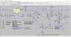
But i am afraid i have to open still yet another can of worms. The two op amps will be in the feedback path (judging by your previous posts) to limit the current. That effectively puts two more integrators in the feedback path. The integrator time constants will be relatively fast, but might not be fast enough. There is also the GBW to consider for the stage that has a gain of 100, which will probably change to a gain of 300 once you reduce the gain of the first op amp. But even at 100 it could cause a problem, and even at a gain of 1 it is still a possibility.

I am not sure how familiar you are with feedback systems, so i'll try to explain this in time-sequential manner, as if each step is viewed in sampled time. This helps to get the idea what could happen more intuitively.

First, assume the circuit is working normally and is not in current limit yet. Then a higher than normal current comes through the 1 ohm resistor. When that happens the first op amp starts to ramp up. When that happens the second op amp starts to ramp up too, but it's ramp might not be a linear ramp like the first because a ramping function of a ramping function is a time exponential function. The time exponential function means the output ramps up a little at first, then the ramp increases. This can easily cause oscillation. But even with out the ramping squared feedback function, the second op amp has to ramp up too, and it's gain bandwidth will be quite limited due to the high gain. What that means is the switching regulator IC feedback pin has to wait for the output of the second op amp to respond favorably, and in the mean time the output of the switcher is still above the current limit set point. Now if the damping factor of the entire network is such that the time response is totally over damped, then the output might simply shoot up and stay higher than normal for a while, then come down, then settle out. So eventually we reach current limit. But if the damping factor is not over damped or just too slow, then the output goes high, the op amp output eventually pulls it down a little, then it pulls it down too far, then it reacts a second time to start to limit the current, then starts to allow it to go high again, etc. This causes unceasing oscillation.
If you like we can go through a calculation using some assumed gains and see what we get, but one general rule usually applies: The feedback circuit should be faster than the error amplifier. In the case above the feedback is much slower than the error amp, so we could see problems at some load or all loads that cause current limiting.
So the first thing to check is basic open loop functionality, then when closing the loop check carefully for oscillation. It may depend partly on the load current or load resistance or whatever is connected as the load, especially capacitor type loads.

Another way to think about this is you drive your car down the highway and step harder on the gas, and you can not see the speedometer, but a friend in the back seat can see it. He has to tell you what speed you are going. It takes time for him to see it and then verbalize the value of the speed, then tell you, and that takes time. In the mean time you've sped up way over the speed limit. By the time he tells you, your going too fast, but then you take your foot off the gas, then slow down too much by the time he tells you you are going too slow, then the process keeps repeating. Now if you know enough to limit your foot movement a little each time, it will be over damped so you'll eventually reach the right speed even if it takes 100 tries, but if you step too hard each time it will never damp out to a constant speed.
On the other hand, if your friend was using a computer connected to your brain that could also read the speedometer, the computer would tell you faster than the engine could respond to your foot. That would get the car to the right speed very very quickly before the car hit a curve in the road going too fast and flew off the road.

I am not sure what you intend to connect to this thing as load, but there are other ways to limit the current too that are much faster. There is a simpler way too but what i dont know is how accurate do you need to set the current limit on this thing. For example, if you set the current limit to 100ma, can you live with 90ma to 110ma, or how about 95ma to 105ma? If so there are faster more stable ways to do this that are guaranteed to work.

I also assumed that your max current would be about 120ma or so, is this correct?
Also, can you stand a little higher resistance for the current sense resistor (drop a little less than 1 volt at full current).
Also, does the current limit have to be adjustable, and if so, how fine tuned does the adjustment have to be?
 
Last edited:
Hi

This is an interesting thread. Out of curiosity, I thought I would try to sim and share the results.
The circuit doesn't seem to be current limiting. Output should be 10v limited to 100mA.
See attached.
 

Attachments

  • LM2576PSU-Ckt.png
    LM2576PSU-Ckt.png
    58 KB · Views: 264
  • LM2576PSU-Sim.png
    LM2576PSU-Sim.png
    19.3 KB · Views: 236
I thought I would try to sim and share the results.
The circuit doesn't seem to be current limiting. Output should be 10v limited to 100mA.
See attached.
Can you please give me the spice model for Lm2576 and Tl082. I searched the net, but couldn't get any.
 
I am not sure what you intend to connect to this thing as load, but there are other ways to limit the current too that are much faster. There is a simpler way too but what i dont know is how accurate do you need to set the current limit on this thing. For example, if you set the current limit to 100ma, can you live with 90ma to 110ma, or how about 95ma to 105ma? If so there are faster more stable ways to do this that are guaranteed to work.

I also assumed that your max current would be about 120ma or so, is this correct?
Also, can you stand a little higher resistance for the current sense resistor (drop a little less than 1 volt at full current).
Also, does the current limit have to be adjustable, and if so, how fine tuned does the adjustment have to be?
My plan is to use it as a bench-top psu for diy projects and components testing. I intent to use it as a variable voltage (1.2v to 37v) as well as variable current source (20ma to 3A), which ever is necessary.

From your post it seems to be very difficult and unpredictable. I'm concerned about accuracy also. To test different circuit and components accuracy of power source is important. I'm a hobbyist, got most of my knowledge (which is not very deep) from internet. Want to make the psu rather than buying one.

Do you have better solutions? Please suggest.
 
Hi again,

I wouldnt mind getting the spice model for the switcher chip too so we can do some experiments in the simulator.

Well, since you want accurate adjustable current like that then the other solution would not work. That solution involves a single transistor and a few other parts so it is very fast, but it is not as accurate. Maybe just a faster op amp then.

A problem with using a 1 ohm sense resistor and 3 amps is the power: 9 watts. But more so the output of the op amps has to be checked to make sure they dont go over the power supply voltage or else it will clip.

Another problem is the last op amp stage probably has to be an actual integrator, not just an amplifier. I dont think you can use a fixed gain like that. We can check this out better once we get the LM2576 spice model.
 
Hi

Here is LM2976 spice model. The subckt file contains both fixed and adjustable models.
I used the built in symbol "opamp2" for the TL082 model.
Have fun. :)
 

Attachments

  • LM2576Model.zip
    3.4 KB · Views: 169
  • TL082.zip
    658 bytes · Views: 136
Last edited:
I'm curious. The original circuit before any modifications looks like it is a constant current supply based on the LM2576. If this is the case, it seems a strange starting point for a general purpose bench supply?
 
Status
Not open for further replies.

Latest threads

Back
Top