Continue to Site

Welcome to our site!

Electro Tech is an online community (with over 170,000 members) who enjoy talking about and building electronic circuits, projects and gadgets. To participate you need to register. Registration is free. Click here to register now.

  • Welcome to our site! Electro Tech is an online community (with over 170,000 members) who enjoy talking about and building electronic circuits, projects and gadgets. To participate you need to register. Registration is free. Click here to register now.

Lipo Battery (confused.)

Status
Not open for further replies.

Gr3mlin

New Member
Hi there. i've been working on a battery level monitor of a 3cell lipo.
its all good making sure the voltage across the + and - doesnt go any less than 9.9vdc but what if 1 cell discharge more.. say to 2.9 and the other are at 3.5... anyhow. i decided to play.

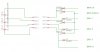
attached is a rather hurry'd plan of what i thought would work.. but it doesnt sort of..
for now forget about diode voltage drop and say all cells are at 3.5v.

Basically what i assumed would happen is that between 'PACK (+)' and 'PACK (-)' i would get a nice perfect across the pack voltage (of course minus the diode drop)
then between 'PACK (COM +)' and 'PACK (-)' i would get 3.5, should get 1 cell reading.
then between 'PACK (COM +)' and CELL(1/2 and 3) i would get a per cell reading.

SO, i tried it 'PACK (COM +)' and 'CELL 1' = 3.5v cool.
'PACK (COM +)' and 'CELL 2' and 'CELL 2' = 7.0v... wait what?
'PACK (COM +)' and 'CELL 3' = 10.5v what on earth...
SO my question is.. how? it all the CELLS are com'd up?..... if anyone call explain it please.
im wondering if because the cells arent really common'd up (via diodes) they are saying.. NOPE! sorry, no going to work! but how and why is what i need to know.

CHeers.
 

Attachments

  • thing101.jpg
    thing101.jpg
    52.1 KB · Views: 208
thanks for taking the time to reply.

I know. im not even sure.
Doesnt matter. i found a rather cheap solution!

CHeers.
 
THere are no circuits that can make cells connected in series behave like cells connected in parallel (that is what you are trying to do with your circuit it will not work). It is also inaccurate because diode voltage drops are not constant, so you could end up inaccurately monitoring a cell and that is dangerous with LiPos since they are so sensitive to overdischarge.

You have only two solutions. YOu can either make a floating measurement circuit for each cell (using switching transistors and transformers and lots of other needless and complicated circuitry or use analog optoisolators, etc.) or you can measure the voltage at the + of each cell with respect to the pack's ground. It is a lot easier to make everything referenced to ground rather than to make a floating measurement connection for each cell. What you do is you measure the difference in voltage relative to ground.

So 1st cell + measured relative to ground = 4.2V
So 2nd cell + measured relative to ground = 8.4V
So 3rd cell + measured relative to ground = 12.6V

THese are the measurements you have, and they are all measured with respect to ground. To find the voltage of the second cell, you take the voltage of the 1st cell and subtract it from the voltage of the 2nd cell:

2nd cell voltage = [2nd cell + measured relative to ground] - [1st cell + measured relative to ground]
=8.4 - 4.2V
=4.2V

For the 3rd cell you go 12.6V-8.4V

You can use an ADC and mathematics to do the subtraction digitally, or you can use an difference amplifier made from op-amps to do this in analog.
--------------------
Now about your circuit...I can see what you are trying to do. It won't work. BUt the way you drew your circuit also has other mistakes because even though the circuit won't work, it is also drawn incorrectly.

1. You have ALL of the positive and negative labels mixed up. The LONG side of the battery symbol is + and the SHORT side is -. Your schematic even has that labelled on the component. But all your net names are labelled the opposite.

FOr example, the label PACK(+) and PACK COM(+) should be PACK(-) and PACK COM(-) since they are connected to the NEGATIVE end of the battery pack. And PACK(-) should be labelled PACK(+) becuase it's connected to the POSITIVE end of the battery pack. Just look at the +/- signs on the cell symbols. I don't know how you got that mixed up.

2. Because of this labelling mistake, your diodes are also connected all backwards too.

3. This also means that to make it easier to read your schematic you should flip the right side of your circuit upside down. Because right now the parts with + to - voltage are going from top to bottom on the left side of your schematic, but they are going bottom to top on the right side. It is confusing.

BUt even if you fix these mistakes, your circuit still won't work. It is possible to correctly draw a non-working circuit. BUt yours is drawn incorrectly and also will not work.
 
Last edited:
Status
Not open for further replies.

New Articles From Microcontroller Tips

Back
Top