Thank you, Steve, MrAl.
It really looks like that I'm back to square one! Anyway, let's try again.
steveB said:
...derivatives and integrals are linear operations.
Yes, they are linear **broken link removed**. But I take linearity of systems and linearity of the operators as entirely different things. Perhaps, I'm missing something.
Moreover, now I think that I came up with bad examples
here. Do you think a capacitor or inductor can be looked as systems in themselves? To me, they are devices and not systems. A good example of a system would be an RC circuit made up of two linear devices, a resistor and a capacitor.
PG1995 said:
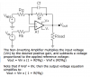
Let's talk about op-amp in general. An op-amp always amplifies the
differential voltage of its inputs. I believe it functions as a linear device when it has a negative feedback because then it adjusts its output in such a way that the differential voltage is almost zero, and its input is also almost zero. In short, the negative feedback is what makes it a linear device. It has been quite a while since I took op-amp course so please correct me I'm wrong or missing some other important detail here.
Do you think what I said above is correct? I'm asking this because I would like to know if I have the fundamental concept correct. It has been quite a while since I studied op-amp.
An
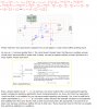
RC circuit in zero-state is a good example of a linear system (likewise, I believe an LC circuit is also a linear system). But I was missing an important term from the definition of a linear system, i.e. "zero-state response".
But an RC circuit which is not in zero-state (i.e. with capacitor charged) is not an example of a linear system.
It has been said that a system represented by a function of type f(x)=mx+b is not a linear system where "m" is slope and "b" is constant. I believe it can also be written as output=m(input)+{output even when the input is zero} where "m" is slope. Please correct me if I'm wrong. By the way, in view of the definitions such a function, f(x)=mx+b, cannot represent a linear system because it contradicts the requirement the system being in zero-state.
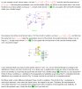
Let's discuss your op-amp
example in a little detail. By the way, if you could come up with a simpler example then it might help. Anyway, please have a
look here.
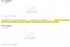
How would you define a linear system in general? Forget the definitions such as homogeneity and additivity for a moment. Above all, one shouldn't confuse a linear system with a mathematical linear function, i.e. line. For example, you can see here that an RC circuit in zero-state represents a
linear system but still you don't get a linear or line graph. Is this correct?
Does a linear system always consist of linear components such as resistors, capacitors, etc? Can a diode (non-linear component) be a part of a linear system?
Regards
PG
Helpful links:
1:
http://www.thefreedictionary.com/linear operator
2: **broken link removed**
3:
**broken link removed**
4:
http://mathworld.wolfram.com/LinearOperator.html
")