Continue to Site

Welcome to our site!

Electro Tech is an online community (with over 170,000 members) who enjoy talking about and building electronic circuits, projects and gadgets. To participate you need to register. Registration is free. Click here to register now.

  • Welcome to our site! Electro Tech is an online community (with over 170,000 members) who enjoy talking about and building electronic circuits, projects and gadgets. To participate you need to register. Registration is free. Click here to register now.

linear voltage regulator

Status
Not open for further replies.

PG1995

Active Member
Hi,

I was reading about a linear regulator using a zener diode, **broken link removed** .

I was going through this example on the same page and got confused when I tried to change numbers.


zener_diode_linear_regulator-jpg.121179


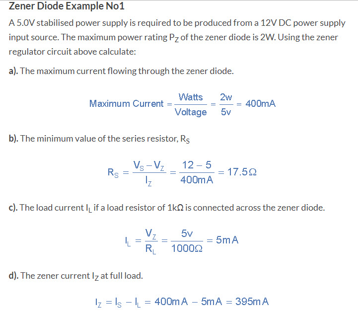
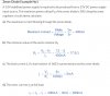
At zener voltage, V_z, the diode becomes an open valve and would permit any amount of current without significant change in the voltage; the current is limited by using a series resistor. In other words, at zener voltage the diode becomes a shunt.

Using the same circuit as shown in the example but assuming that R_L is 16.7 Ω and requires 5 V for its operation; it would take 5/16.7=300 mA. The maximum current supplied is 400 mA.

Would 300 mA pass through the load R_L and the rest 100 mA through zener diode? I assume that your answer is 'Yes'. Compared to the load resistor, R_L, the zener offers less resistance so more current should pass through it. Where am I going wrong? Thank you for your help.


Helpful links:
1: **broken link removed**
2: **broken link removed**
3: http://www.reuk.co.uk/wordpress/electric-circuit/zener-diode-voltage-regulator/
Zener diode specs such as zener voltage, mimum zener current:
4: http://electronics.stackexchange.co...rent-if-it-is-not-explicitly-specified-in-the
5: http://www.digikey.com/en/maker/blogs/zener-diode-basic-operation-and-applications
 

Attachments

  • zener_diode_linear_regulator.jpg
    zener_diode_linear_regulator.jpg
    112 KB · Views: 328
Would 300 mA pass through the load R_L and the rest 100 mA through zener diode?
Yes.

Where am I going wrong?
You are confusing yourself by making this statement:
Compared to the load resistor, R_L, the zener offers less resistance so more current should pass through it.

A zener diode does not follow a simple Ohms Law relationship.

If you look at the specifications of zener diodes, they usually give a dynamic resistance, or zener resistance which is usually low, just a few Ohms.
This resistance represents the slope of the zener V-I characteristic.
If you wanted to produce an equivalent circuit for a zener, you would have this zener resistance in series with a constant voltage source.

JimB
 
At zener voltage, V_z, the diode becomes an open valve
This is where your thinking is wrong. At the zener voltage the valve starts to open and is fully open a few 100s of mV higher. So the zener will conduct as much as is needed to maintain 5V. If the load takes the whole 400mA then the zener will not even open a little bit - conduct nothing.

Mike.
 
Thank you!

If you look at the specifications of zener diodes, they usually give a dynamic resistance, or zener resistance which is usually low, just a few Ohms.
This resistance represents the slope of the zener V-I characteristic.

That was a good hint.

This is where your thinking is wrong. At the zener voltage the valve starts to open and is fully open a few 100s of mV higher. So the zener will conduct as much as is needed to maintain 5V. If the load takes the whole 400mA then the zener will not even open a little bit - conduct nothing.

You are correct. This is where I was having it wrong.

I was thinking more in terms of the following picture which is misleading and says that the voltage remains constant.

1571448604135.png


Source: http://www.electronicshub.org/zener-diode-tutorial/

Beyond break down region, zener diode behaves like a dynamic resistance (if V is to remain almost constant then R needs to change, V=IR) and it decreases as the current increases but this does not mean that the voltage remains constant. If zener voltage is 5 V and minimum required breakdown current is 5 mA, then if the current becomes 20 mA, the voltage might read, say, 5 V plus 100 mV. The dynamic resistance is maximum around the knee of breakdown region.

Now coming back to the original question, suppose that the load resistor, R_L, is not connected and the maximum allowed current of 400 mA is passing through the zener diode. The voltage around the zener would be 5V plus few hundreds of mV. When R_L is connected, the current starts passing through it. If at zener voltage 5V, mimimum required current for breakdown is 5 mA, and if at 5V R_L takes 300 mA then it would steal away 300 mA which was passing through zener. Now zener's voltage would decrease more toward 5V.

Helpful links:
ZR 1: http://toshiba.semicon-storage.com/...e/what-is-the-impedance-of-a-zener-diode.html
ZR 2: http://electronics.stackexchange.com/questions/31878/differential-resistance-for-a-zener
ZR 3: http://electronics.stackexchange.co...rz-is-this-graph-or-the-values-for-rz-correct

Question 1:
In the link above, ZR3, why the author is saying V_A ≃ V_Z? Actually the cathode, K, is being applied the voltage so it should be V_K ≃ V_Z. Perhaps, it's the convention to designate the voltage like this.

1571449404487.png


When load resistor changes:
As long as the load resistor doesn't take away all of the current and leaves at least 5 mA for the zener, the voltage would stay at 5V.

When supply voltage changes:
You might need to change the series resistor to limit the current otherwise zener diode would go bad. Assuming the current doesn't exceed the maximum allowed current for the zener, changing supply wouldn't affect output voltage as long as zener diode gets it 5 mA.

It is said on this page, **broken link removed** :
"We remember from the previous tutorials that the DC output voltage from the half or full-wave rectifiers contains ripple superimposed onto the DC voltage and that as the load value changes so to does the average output voltage. By connecting a simple zener stabiliser circuit as shown below across the output of the rectifier, a more stable output voltage can be produced."

It means a zener diode regulator gives a more smooth voltage output. In this case, rectifier's output should be a little bit higher than zener regulator's output. For example, if the regulator's output is 5V then rectifier's output should be 7V. The zener's voltage doesn't drift away much from its nominal value if the current through it changes therefore the ripple from rectifier wouldn't change the output voltage across zener regulator much.

I hope I don't have it all wrong. Thank you!


Helpful links:
1: http://www.electronics-notes.com/ar...diode-datasheet-specifications-parameters.php
2: http://www.digikey.com/en/maker/blogs/zener-diode-basic-operation-and-applications
3: http://electronics.stackexchange.com/questions/90690/calculating-resistance-for-zener-diodes
4: http://toshiba.semicon-storage.com/...e/what-is-the-impedance-of-a-zener-diode.html
5: http://electronics.stackexchange.co...rz-is-this-graph-or-the-values-for-rz-correct
6: http://www.learningaboutelectronics.com/Articles/What-is-the-resistance-RZ-of-a-zener-diode
7: Decoupling capacitor: http://en.wikipedia.org/wiki/Decoupling_capacitor
8: Capacitive coupling: http://en.wikipedia.org/wiki/Capacitive_coupling
 
Last edited:
The voltage of a zener is specified at a particular current. If you feed it with a constant current source, it will be much more accurate. Unfortunately, a zener is an important part of a constant current source. So, if your raw dc voltage source varies a lot, you may need to cascade a poor "constant" current source built with a zener (or even a standard diode) into a zener to regulate voltage. And even a second cascade if your voltage regulation needs are high and raw dc fluctuates a lot.

Alternatively, you can buy one of many well made voltage references or regulators instead of using a zener.
 
Status
Not open for further replies.

Latest threads

New Articles From Microcontroller Tips

Back
Top