Continue to Site

Welcome to our site!

Electro Tech is an online community (with over 170,000 members) who enjoy talking about and building electronic circuits, projects and gadgets. To participate you need to register. Registration is free. Click here to register now.

  • Welcome to our site! Electro Tech is an online community (with over 170,000 members) who enjoy talking about and building electronic circuits, projects and gadgets. To participate you need to register. Registration is free. Click here to register now.

Limiting Comparator Swing Voltage

Status
Not open for further replies.

ACharnley

Member
Hi,

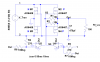
For the attached schematic I need to limit the gate voltages for the N/P Fets. For the N this is simple however for the P gates the voltage swings to ground via the comparator. Assuming a Vcc of 20V created by a resistor/zener between Vout and GND, what's the correct method to ensure the comparator swings between Vout and Vcc?
 

Attachments

  • Screenshot from 2017-09-16 14-16-56.png
    Screenshot from 2017-09-16 14-16-56.png
    31.1 KB · Views: 155
What's Vcc?
That circuit looks familiar. ;)
You can limit the gate voltage by putting a resistor in series with the comparator output.
For example, a 10kΩ resistance would cut the maximum gate voltage in half.
 
Ah, you've took it to be a N -channel, it's a P so the gate voltage can't be sunk lower than Source - Vgs rating. When the comparator drives it to ground, that's a problem.
 
Ah, you've took it to be a N -channel, it's a P so the gate voltage can't be sunk lower than Source - Vgs rating. When the comparator drives it to ground, that's a problem.
No, I know it's a P-MOSFET.
The added resistor creates a voltage divider that reduces the P-MOSFET Vgs voltage, as you want.
As I noted, an added 10kΩ, with the gate-source 10Ω resistor, reduces the ON Vgs voltage by 1/2.
 
I think the goal is to; get power from a transformer and regulate a DC voltage.
Here are two simple versions.
upload_2017-9-16_21-19-51.png
 
I think the goal is to; get power from a transformer and regulate a DC voltage.
It's not a regulator.
That circuit uses MOSFETs as ideal diodes in a bridge configuration, as discussed here.
It has more of an advantage over standard diodes at low transformer voltages (say below 10Vac), than at the 40Vac in the TS's circuit.
 
Dropping the gate voltage by half isn't a solution. With a P-channel FET the max gate voltage is the delta between the drain and Vgs rating NOT ground and Vgs rating (unlike N-channel).

So if 40V is applied to the drain and the Vgs rating is 20V then the gate must not drop below 20V (i.e be shunted to ground).

In the picture I've attached you can see how the P-channel is protected.

The issue with the active design I'm using is the comparator swings the gate voltage to ground.
 

Attachments

  • ZenerBridge.GIF
    ZenerBridge.GIF
    5.8 KB · Views: 119
With a P-channel FET the max gate voltage is the delta between the drain and Vgs rating NOT ground and Vgs rating (unlike N-channel).
Don't understand that. o_O
It either case its the maximum Vgs that's of interest, not Vgd.

Here's a simulation with 30kΩ resistors in each comparator output.
That reduces the maximum Vgs of both MOSFETs to <14V.

But note that this MOSFET bridge has very little efficiency advantage over a Schottky diode bridge for a 40Vac input.
It adds a lot of complexity for very little gain.
Why do you want to use that circuit?

upload_2017-9-17_12-6-8.png
 
For 6V AC.

You're right on the resistors and yet I tried that first and it didn't work in real-life. There's a lot of overshoot going on causing greater efficiency loss via shorts.

I created three circuits with a large smoothing capacitor and fixed wire resistor to compare the efficiency. Measurements by oscilloscope:

1. 4x 5819's - 5v - 5.5v (5.25v average)

2. semi active, IRF7103: 5V - 5.8V (5.4v average)

3. active, DMHC4035LSD, LM393: 4.7v - 5.4v (average 5.278v)

This was with much faffing to the above circuit, which especially requires two 473 capacitors between the resistor dividers and ground. This may be specific to the DMHC4035LSD characteristics. I found the LM393 was overly sensitive to Vin chatter which would cause false outputs to turn the FET's on. Looking at it, it would probably work to use a boost for stable voltage to the comparator.
 
Status
Not open for further replies.

Latest threads

New Articles From Microcontroller Tips

Back
Top