Continue to Site

Welcome to our site!

Electro Tech is an online community (with over 170,000 members) who enjoy talking about and building electronic circuits, projects and gadgets. To participate you need to register. Registration is free. Click here to register now.

  • Welcome to our site! Electro Tech is an online community (with over 170,000 members) who enjoy talking about and building electronic circuits, projects and gadgets. To participate you need to register. Registration is free. Click here to register now.

Lightning trigger

Status
Not open for further replies.

Lighty

New Member
Hi All

I'm buzy building a lightning trigger that can be connected with my Canon 500D D-SLR.

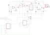
I have tested (not with actual lightning yet but with another camera flash) Circuit 2 without the 555 one shot section, but I'm sure with the one shot section added it will be a bit better.

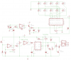
But here is my question, do you think I need to add a amp/gain section as shown in Circuit 1, or will this be a waste?

I'm hoping to eventually use the circuit (without the one shot) on a PIC with an LCD.

Any feedback or assistance will be extremely greatful.
 

Attachments

  • circuit 2.png
    circuit 2.png
    9.5 KB · Views: 814
  • Circuit 1.png
    Circuit 1.png
    11.2 KB · Views: 414
Depends upon how far away the lightning is and its brightness as to whether you need added gain, but probably not. Best way is just to try with actual lightning.
 
Thanks Crutschow, what you say is so true.

I've decided I will leave the Amp section in as it will be adjustable it the gain can be turned down if required.

I'm also thinking of of adding a 2 LED BAR graphs, one showing the actual level of the light (output from opamp IC1A) and another showing the "trigger adjustment level" (+ input into IC1B), not shown in schem yet.

This should hopefully give me a better indication of the levels at a quick glance, Any comments?

But I have one more possible problem:

I can set the camera to have a certain shutter speed, which when the camera is triggered by the "lightning trigger circuit" it will take the photo and the shutter will close, if the trigger circuit is still HIGH (triggering mode) it will just taking pictures, not a problem. But if I set it to bulb (holds shutter open until trigger released), the circuit may just hold the shutter open if there is alot of lightning around, causing the picture to be over exposed. How could I use another 555 to create a max time threshold?

And since speed is a use concern, by adding all these extra components/section does this slow the actual reponce time of the circuit? As my camera already has a lag time of about 70ms, and need to keep it as low as possible, hopefully under the 100ms mark?

Thanks in advace.
 

Attachments

  • circuit 3.png
    circuit 3.png
    25.2 KB · Views: 367
You could just trigger a FF, such as a 4013, by the trailing edge of the 555 pulse period (invert the pulse to the FF CLK input). The output of the FF could then be used to inhibit further triggers. You could manually reset the FF with a PB switch or another 555 delay for the next picture.

The circuit delays are in the microsecond region, so will add no significant time to the 70ms camera delay.

Alternatively, you can just use a 556 and configure the 2nd stage as a bistable multi ( flip-flop ) to save a chip.
 
Thanks Guys

I'm battling here a bit but think I have the idea? Only problem is I'm not sure how to configure/wire up the 2nd 555 that resets the 4013, as when its (555) RESET is released by the 4013 the output needs to stay LOW until timer is up, then high output will inturn reset the 4013, inturn releasing the top 555, allowing the circuit to be ready for the next bolt of lightning.

Brownout, if the 2nd part of the 556 acts as a flip flop, then what would reset it and controll the delay?


As you can see in the schem, I'm a but stumped with IC5. Am I correct in saying pin6 on IC4 should be grounded?

Thanks
 

Attachments

  • circuit 4.png
    circuit 4.png
    18.9 KB · Views: 334
Dude, click on "Circuits" at the top of the page. Find the design contest entry #3 that's titled something like "555 as a bistable multivibrator." I think he shows how to configure it properly. Good luck :)
 
Status
Not open for further replies.

Latest threads

New Articles From Microcontroller Tips

Back
Top