Continue to Site

Welcome to our site!

Electro Tech is an online community (with over 170,000 members) who enjoy talking about and building electronic circuits, projects and gadgets. To participate you need to register. Registration is free. Click here to register now.

  • Welcome to our site! Electro Tech is an online community (with over 170,000 members) who enjoy talking about and building electronic circuits, projects and gadgets. To participate you need to register. Registration is free. Click here to register now.

light triggered switch...

Status
Not open for further replies.

wrybread

New Member
I'm building one of those arcade style basketball games where you get 30 seconds to shoot a bunch of mini basketballs. I have everything built except the sensor that detects when you sink a basket. I thought the best way to do it would be to have a beam of infrared light interrupted by the ball falling. The switch can be momentary (well, as long as it's at least 100 milliseconds or so), as the software can interpret it from there.

Does anyone have any tips?

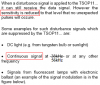
I found this circuit, and tried building it, but I'm not getting any reaction from it:

http://www.oscarcontrols.com/coinswitch/

I'm pretty new to circuits and have never built one using an IC, so it's entirely possible the problem is with me. But in this circuit, the light gap is very small (the width of a quarter). Do you think it would be adaptable to 2 feet or so?

Thanks for any help.

And if anyone's curious how I made the game interface with the PC, I used a Phidget interface, and wrote the game in Flash.
 
Hmm, i'd say that if you were using this over a longer range, it might be best to use a laser diode instead. Also, you may need a light pipe on the phototransistor to help shield it from external light.

If you can't get a laser diode, or don't want to use that, a phototransistor with an infra red filer (they appear black) might be best, as this will block external light much better. Also try to use a good high power infra red emitter.
 
Hey! Didn't I answer you in the other website's forum? :?:
Yeah, you need a phototransistor that is not sensitive to ambient light, that clear one certainly is. Or else use it in darkness. He, he. :lol:

You can reduce the value of R4 to 47 ohms for much more range and quickly kill the battery too.

You probably need to modulate the IR beam with an oscillator, and use a 3-pin IR receiver module, like used for TV remotes.
I haven't tried pressing a button on my TV remote for the length of a basketball game, to see if its battery lasts that long. Its range is about 30m, so the IR current could be reduced to extend its battery's life. :lol:
 
You probably need to modulate the IR beam with an oscillator, and use a 3-pin IR receiver module, like used for TV remotes.

Once, I tried to interface a 3-pin IR receiver module with a 555 monostable for a similar circuit as posted above but it didn't work out. The problems were:
1) DC voltage is always present on the output of the IR receiver wether its receiving signal or not. Ideal case would have been for the output to go high when receiving and the voltage should disapear when not receiving.

2) Because it was receiving modulated IR, the output was also modulated and therefore difficult to interface with my counter circuit.

Now, I have decided to abandon IR and try out laser. but if you have any idea how I can interface the 3-pin IR receiver module to generate pulse that can be counted on my counter circuit. I'll appreciate that.
 
folarinv said:
You probably need to modulate the IR beam with an oscillator, and use a 3-pin IR receiver module, like used for TV remotes.

Once, I tried to interface a 3-pin IR receiver module with a 555 monostable for a similar circuit as posted above but it didn't work out. The problems were:
1) DC voltage is always present on the output of the IR receiver wether its receiving signal or not. Ideal case would have been for the output to go high when receiving and the voltage should disapear when not receiving.

They work the opposite way, they are HIGH normally, and go LOW when they receive 38KHz modulated IR. If you need it the other way, just add a simple transistor inverter.

2) Because it was receiving modulated IR, the output was also modulated and therefore difficult to interface with my counter circuit.

Don't use a coded remote control for it, just use a plain 38KHz signal, it should work fine then!.
 
Nigel Goodwin said:
They work the opposite way, they are HIGH normally, and go LOW when they receive 38KHz modulated IR. If you need it the other way, just add a simple transistor inverter.


Or just adjust your software to look for a low signal, instead of a high signal.
 
Nigel Goodwin said:
folarinv said:
You probably need to modulate the IR beam with an oscillator, and use a 3-pin IR receiver module, like used for TV remotes.

Once, I tried to interface a 3-pin IR receiver module with a 555 monostable for a similar circuit as posted above but it didn't work out. The problems were:
1) DC voltage is always present on the output of the IR receiver wether its receiving signal or not. Ideal case would have been for the output to go high when receiving and the voltage should disapear when not receiving.

They work the opposite way, they are HIGH normally, and go LOW when they receive 38KHz modulated IR. If you need it the other way, just add a simple transistor inverter.
I'll describe a test I carried out. I connected my 3-pin IR receiver (sharp)to 9V supply through a 470ohms resistor and 47uf bypass cap. Then I used a LED to monitor the output and also a digital multimeter. when not receiving, my LED remain ON and steady. My DMM read 7V. When it starts to receive, theLED starts to blink fast and the DMM still read about 6.7V, DC


2)
Because it was receiving modulated IR, the output was also modulated and therefore difficult to interface with my counter circuit.

Don't use a coded remote control for it, just use a plain 38KHz signal, it should work fine then!.
[/quote]

I used a TV remote control because of the range readily achievable with it
 
IR modules have more sensitivity to bursts of modulation. Their AGC reduces the gain for continuous modulation so they aren't sensitive to the ultrasonic switching of compact flourescent lamps.
 

Attachments

  • ir_receivers2.png
    ir_receivers2.png
    14.8 KB · Views: 514
folarinv said:
I used a TV remote control because of the range readily achievable with it

Which is fair enough! - BUT you need to deal with the digital data at the receiving end, which you weren't doing.

A 555 with a driver transistor feeding an IR LED will give a similar range to an IR remote, basically it's doing the same thing. Or you could use a PIC (as in my tutorials), which would give you the option of coding if you wanted - but for a plain 38KHz a 555 would be fine.
 
Status
Not open for further replies.

Latest threads

New Articles From Microcontroller Tips

Back
Top