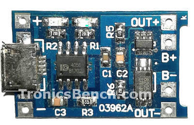
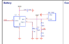
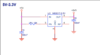
Hello everyone, I am designing a product which needs a Li-Po battery and I need a circuit to charge it. I am confused as to how do I charge the battery as well as use it as a power source within the same circuit. What I mean to say is, how is it that a phone, or any rechargeable device know that the battery is being charged and knows when the current needs to be sent into the battery?
Can someone share how a circuit looks like this? Will the Battery charging IC I choose automatically have this feature? Or do I need a special component that does it for me? Please do let me know. Thank you
Can someone share how a circuit looks like this? Will the Battery charging IC I choose automatically have this feature? Or do I need a special component that does it for me? Please do let me know. Thank you
")