Continue to Site

Welcome to our site!

Electro Tech is an online community (with over 170,000 members) who enjoy talking about and building electronic circuits, projects and gadgets. To participate you need to register. Registration is free. Click here to register now.

  • Welcome to our site! Electro Tech is an online community (with over 170,000 members) who enjoy talking about and building electronic circuits, projects and gadgets. To participate you need to register. Registration is free. Click here to register now.

LI-PO charger connections

Status
Not open for further replies.
NO part ID's?
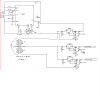
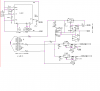
the regulators are LT1083/12 and LT1083/5. really need a 9 v for charger but 12 shoudl do it but input voltage is 12-14v. need to address this. perhaps a 7809 would be better? only need 1amp as the battery max charge should be maxed at .700 as per recommendations.
 
If you have 12V into a linear regulator that has an output of only 5V then you are heating the world with 7W if your output current is 1A.
7W is a lot of heat in a little voltage regulator.
How will you get rid of that much heat?
 
have you heard of global warming??


LOL
will look for a LDO for say 9v instead of 5 or decrease input voltage seeing hoe the input is 12 v vehicle or 220 ac
I contemplared and kinda looked for a reguilator for 9 volts (this is for the charger portion)
 
data sheet about voltage supply

In the S8232 diagram it shoiws what looks like a duel polarity supply?
has + - and GRD??confused
revised idea for powering this Li-PO charger. two input supplies 230v and vehicle (12-14)
need heat sinks for sure
 

Attachments

  • battery power.PNG
    battery power.PNG
    25.7 KB · Views: 436
Hi MrDEB,

once again: the S8232 is not a LIPO charger, but a LI-Ion charger IC.
 
back to this circuit for a charger. the paper shows a graph of charging rate etc. LOOKs good but will it perform for this app (charge a 2 cell 9AH battery pak
Lithium Ion, Lithium Poly Charger Circuit
Audoguru says it won't??
doing some more searching for charger.
question- won't the S8232 allow this charger to fully charge instead of only 70%??
 
Mr DEB,
Correct your latest circuit quickly before a nOOb sees it and makes it.
IT IS MISSING VERY IMPORTANT RECTIFIERS!

The S8232 is not a battery charger. It is a battery protection IC. A battery charger has a current limiter and voltage regulator. The protection IC does not have them and simply shuts off if it detects a voltage or current that is too high.

The battery charger circuit with the LM317 might work. The transistor limits the current and the resistors make a good voltage regulator.
The circuit must have a timer to shut it off because trickle-charging a Lithium battery is not allowed.
 
I knew that circuit looked funny.
As for the charger, won't the management IC S8232 control the charger output with the mosfets?
Maybe add an op amp that shuts the charger off when current drops to preset level or ??
need to contemplate this
any suggestions? and wondering why there are very few circuits showing only one battery?
 
revised w/ diodes

corrected hopefully correct as I am headed to church then breakfast (its valentines day)
 

Attachments

  • battery2.PNG
    battery2.PNG
    29.9 KB · Views: 305
Without having a charger circuit, the management IC will allow a charging current that is much too high then the voltage will become too high and the management IC will shut off the charging long before the battery is fully charged.
The management IC protects the battery against a defective charger or a short circuit.
 
The battery protection IC also balances the charging of the two cells so that one does not get over-charged.
I corrected your schematic.
 

Attachments

  • lithium charger correction.PNG
    lithium charger correction.PNG
    12.7 KB · Views: 452
We is going to have to rename you, instead of audioguru how about OLD EAGLE EYE

thanks, I see my mistake
will make corrections
 
added car adapter and 220 inputs

This circuit is taking shape. Just hope its right.
Looks right but then several pair of eyes may find errors. Like OLD EAGLE EYES (audio guru)
want to isolate the batteries from the aux outputs (reg2 &reg3) but think that the secondary windings have current when vehicle connected (enabled by switch sw2.
the two triacs are probally not needed, one would do but the two will shut off ALL 230V inputs. SAFETY?
 

Attachments

  • battery backup.PNG
    battery backup.PNG
    44.3 KB · Views: 245
Your AC power supply uses half-wave rectifiers instead of full-wave rectifiers. It is missing big filter capacitors so the rectified voltages are jumping up and down.
 
Last edited:
One of those forgotton items. I usually use a fullwave bridge rectifier but why not here?? brain fart.
Filter caps - never even occured to me - thanks.
I took out one of the Triac, opticouplers. Takes up too much landscape on pcboard.
will add suggestions and repost.
 
revised power supply

removed one opti/triac, added fullwave rect. and added filter caps.
might be wrong on cap values?
 

Attachments

  • battery management.PNG
    battery management.PNG
    39.1 KB · Views: 283
Status
Not open for further replies.

Latest threads

Back
Top