Electro Tech is an online community (with over 170,000 members) who enjoy talking about and building electronic circuits, projects and gadgets. To participate you need to register. Registration is free. Click here to register now.
Welcome to our site! Electro Tech is an online community (with over 170,000 members) who enjoy talking about and building electronic circuits, projects and gadgets. To participate you need to register. Registration is free. Click here to register now.
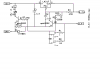
am assuming this is correct? using a battery management IC S-8232.
the batteries are 9000mAH battery pack.
never worked using such an IC.
any suggestions
OUPS! looked at diagram again and see what your talking about.
I feel really stupid to say the least but if one dosn't ask the question then the person is really stupid and not curious.
Something I missed as well?
Looking at the data sheet fig 8 page 18, its a duel polarity power supply
12v+/GRD/12V-
assuming they are referring to EB+ and EB-
I guess all I need is a 7812 and a 7912 to charge the batteries but not real sure having never worked with LI-PO batteries.
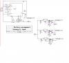
However I made a PCB design for it. Board dimensions are 0.98X0.8".
If you like it PM me your email address. I'll provide the Eagle files for it.
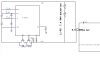
The power supply can't be dual (symmetric). There are just two connections for external power. EB+ stands for the positive rail and EB- stands for ground.
Just don't connect C3 and VSS to the negative rail of the power supply.
Then where to connect C3/GRD to? if not the V- of the power supply. Am assuming just a 7812 for power?
I don't use eagle (I should but its a long learning process etc and at my age I am doing good just learning Swordfish basic/PIC programing.
Will use your eaxample for doing this charger but its ALL smd.
closer look but still?
the orginal schematic I have shows a AO8820 FET. cross to I pretty sure is a KO8822 at Mouser Digi-Key - 785-1097-2-ND (Manufacturer - AO8820)
which will work or is either better the IRF 7401 or the AO8820
You have the 12V power supply connected to the battery protection IC with backwards polarity.
The battery protection IC is designed for two 3.7V lithium battery cells, not two 7.4V batteries as you show.
12V is too high to charge a 7.4V battery so the 12V regulator will get extremely hot.
closer look but still?
the orginal schematic I have shows a AO8820 FET. cross to I pretty sure is a KO8822 at Mouser Digi-Key - 785-1097-2-ND (Manufacturer - AO8820)
which will work or is either better the IRF 7401 or the AO8820
the A08820 and the IRF7401 are identical in performance. The IRF7401 has one big advantage over the A08820 - the pinout. The IRF7401 has one gate pin and three source pins on one side, and four drain pins on the opposite side. The A08820 has source, gate and drain pins arranged in another sequence: D, S, S, G, G, S, S, D (from pin1 through 8). The IRF7401 has them in the following sequence: S, S, S, G, D, D, D, D.
The latter transistor is much easier to route on a PCB design. (May be it's cheaper as well. I didn't read Digikey's price). The IRF7401 is 50 Cents.
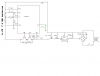
Now you have an LM317 battery charger circuit designed for a lead-acid battery. It senses the max allowed voltage on the battery of 8.4V but it shuts off too soon when your Lithium battery is only 70% fully charged. www.batteryuniversity.com talks about battery details. Maxim has some battery charger ICs and their datasheets explain everything they do.
If you want to charge Lithium Polymer, there are some very simple chips to do that. MAX1555 and MCP71833. I have a nice little MCP71833 board I made up for charging the LiPoly cells I've gotten from recycled electronics. Like mentioned, to charge these things, they are charged up to 4.2V for each cell and then fed current to top it up.
This is not Lithium Ion, though. They are different.
Maybe I don't need an aditional charger seeing how the S8232 does the same thing? just supply 12v to the B+ and B_ inputs as per BocUKs schematic?
here is the link to the charger I had posted, says its for Lithium Ion batteries SHDesigns - Lithium Ion Charger
The lead-acid battery charger does not limit the current until it is the 2.2A max for the LM317 (but your battery protection IC does).
It shuts off the charging when the lead-acid battery is fully charged because then its voltage is at the setting of a fully charged lead-acid battery.
The author doesn't know that a Lithium battery is different because its voltage reaches its max allowed voltage when the Lithium battery is only 70% fully charged.
the two other regulators are for 10 &15w 5v outputs.
the two additional outputs are no big deal. want to get the LI-PO charger circuit down pat first
J1 goes to batteries
This site uses cookies to help personalise content, tailor your experience and to keep you logged in if you register.
By continuing to use this site, you are consenting to our use of cookies.