saturn1bguy
New Member
I would like to have a good answer when one of the kids asks me why. Up to now I have made do with saying that LEDs are greedy and without the limit resistor they may burn out. More of a what will happen then a how or why.
Looking at a typical LED datasheet, e.g. the one Audioguru posted, shows that Vf is advertised at a particular If. Looking at the curve, If runs away pretty quickly as Vf is increased.

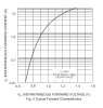
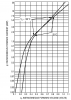
")
