Continue to Site

Welcome to our site!

Electro Tech is an online community (with over 170,000 members) who enjoy talking about and building electronic circuits, projects and gadgets. To participate you need to register. Registration is free. Click here to register now.

  • Welcome to our site! Electro Tech is an online community (with over 170,000 members) who enjoy talking about and building electronic circuits, projects and gadgets. To participate you need to register. Registration is free. Click here to register now.

LED VU meter not sensitive enough at low volumes

Status
Not open for further replies.

Super-Dave

Member
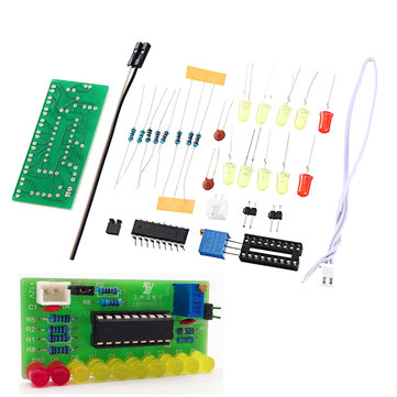
I am TRYING to build a LED VU Meter to serve as a basis for a spectrum analyzer. Before I move onto the bandpass filters, I need to conquer the actual display. It is based on this design I found on the web.
1643916805068.jpg

It's 12v DC powered. R1 is 100k, R2-10 is 470k, D1-10 is 1N4148, LEDs are 3mm 2v or 3v (depending on the colors). Q1 is a 2N3904 NPN transistor.
It works, sort of. I have it hooked up to an unused pair of speaker outputs of a car stereo (4 channel, 2 for speakers, 2 for the display). My issue is: It isn't sensitive enough. It'll only start showing if the music is cranked to 25 (maxes out at 63, distortion ensues, 50 is best). Normal listening volume is 15-20.

This is my 3rd attempt now. 1st was without a transistor, essentially a LED diode/resistor ladder. It worked but only barely at max volume. 2nd attempt was with LM3914/3915's. Never made it past the breadboard stage, all sorts of goofy results. Back to the diode ladder.

I have tried to use an AC voltage doubler on the speaker outputs (with the transistorized meter) little success, then triple, then quadruple. I used 1N4148s instead of 1N4001s because that is what I had available.
1644205012610.jpg


They did manage to boost the LEDS to higher values but again ONLY at high volumes, never able to increase the low end sensitivity below 25. Add in a simple low pass filter and I need it cranked to 30 or more to get just 1 light to flicker. This won't work in my car. I would need obscene volumes just to see it, enough to piss off the neighbors and draw unwanted attention from the cops.

Is there a way to amplify the incoming signal to get it to light up at low volumes?

Thank you in advance for your responses.
 
The big problem with the basic circuit is that nothing will happen until the voltage reaches the point the rectifier and transistor conduct, at around +1.2V

Try adding an input bias network:
Two diodes in series, cathode connected to ground and with a resistor (eg. 1k or 4k7) from anode to power positive, then with a 10k resistor from anode to the existing input.

That will hold it at or close to the threshold where the rectifier and transistor base conduct.

Then use a series capacitor from the audio to the existing input point, so that DC bias is not affected; eg. 10uF with positive to the bias / rectifier diode.

It's still very crude, but should work a lot better than at present!
 
Try reducing the value of R1.
 
Try adding an input bias network:
Two diodes in series, cathode connected to ground and with a resistor (eg. 1k or 4k7) from anode to power positive, then with a 10k resistor from anode to the existing input.

Then use a series capacitor from the audio to the existing input point, so that DC bias is not affected; eg. 10uF with positive to the bias / rectifier diode.
Like this? Does the cap go between the bias network and the VU meter, or between the stereo and then to the bias?

IMG_20220207_204058579_HDR.jpg


Please forgive my "crude" drawing, I don't have access to a decent computer or fancy software, these days I'm just using a cell phone. Crude is kinda my forte. It'll all be hidden inside a box & a tinted plastic lens anyway. As long as it works, who cares how it works or what it looks like.

And for what it's worth, I amended the original design to include a 47uF electrolytic cap between the amplified input to the led/diode ladder (+ to lights, - to ground) to serve as a peak detector. Any higher and the decay lasts too long and it diminishes the length of how many lights go on, any less and it flickers. There's a slight flicker to it now but I can live with it. Yes it's crude, but effective.
 
The idea is to bias the existing parts, to avoid the 1.2V input requirement of the original design:
ps. Ignore the Schottky diode symbols, they were just convenient. Use 1N4148s, as in the rest of the circuit.


InputBias.jpg
 
Ah, thank you rjenkinsgb! I'll implement this tonight when I get off from work & try it out.
But why use 2 diodes? Is there a need for the redundancy? I get that it adds voltage to the input to bootstrap the threshold values of the 1st LED/diode pair, I'm just trying to understand why I need 2 of them.
 
Basic_VU.jpg


There are two "diode drops" in the basic circuit.
It needs around +1.2V at J1 before the transistor will start to conduct and cause any display - that means quite a high audio level to get anything.

By biasing the input with two diodes equivalent voltage so it's near the conduction point, it should take very little signal to produce some activity in the LEDs.

You could even use three series diodes, then use another diode in place of the 10K bias resistor?
That would double the sensitivity, as it would "clamp" the negative excursions of the input signal to around 1.2V, doubling the positive peaks.

Try two diodes and the resistor first; different resistor values will probably change the sensitivity - higher value like 10K will give a kind of AGC, possibly giving a better approximation of a log display?

Lower values, down to eg. 470 Ohms, will keep the DC level nearer constant and the peaks higher.
 
My VU meter is very sensitive with an active rectifier that uses an opamp and has no voltage loss like your ordinary rectifier.
My active Rectifier is also a Peak Detector that has a very fast attack and a slow release using a transistor instead of a diode. Its output can turn on your output transistor.
 

Attachments

  • peak detector.PNG
    peak detector.PNG
    16.2 KB · Views: 260
Follow up addendum:
Holy shazbutt! It works!!!
Of course I bread boarded it, and after the 1st attempt yielded 6 lit LEDs with zero input, I started "tweaking" the values, tune it if you will. I finally settled with a 30k resistor instead of 1k, 1k instead of the 10k, a 220uF polarized cap in place of the 10uF, and the 2 diodes in parallel to ground instead of series. Otherwise it kept burning out one or the other. I tried 1 solo by itself but it died within minutes. 2 diodes to ground in parallel works for some reason.

But it works! It starts flickering around 2-5, depending on the song and what the bass level is set to, at 25 it swings 5-7 LEDS and max pushes it all the way to full tilt. I can work with this!

Later I'll write up and post the entire diagram for all to see, use and enjoy.

Thank you again rjenkinsgb!
 
My VU meter is very sensitive with an active rectifier that uses an opamp and has no voltage loss like your ordinary rectifier.
My active Rectifier is also a Peak Detector that has a very fast attack and a slow release using a transistor instead of a diode. Its output can turn on your output transistor.
Audioguru, a few questions:
1. Would I be correct in assuming that C8/R13 in your circuit are responsible for the slow decay rate on your peak detector? I've toyed with the cap values on the LED string, anything higher than 47uF gives me a sluggish decay, less than that and it flickers noticeably. I like it quick and responsive. If I decreased the values for these components, could I quicken the release response?
2. Could I use a TL074 or an LM328 instead of the MC33171? Because that's what I have available for my bandpass filters. Since it's stereo (left & right channels each get their own set of lights), it's easy enough to use a multiplex op-amp.
3. If I were to include bandpass filters into this circuit, would you recommend placing them prior to the peak detector, following the detector but before the transistor amplifier, or following the amp? I have a spare pair of op-amps on the chip, no reason why I shouldn't use them. (Yes, I have a 15v +/- dual power supply module for the split rail TL074s).
1) My release is 1/10th of a second which prevents low frequencies from fluttering the dropping voltage.
Since you do not show your load then I do not know your timing.
2) One opamp of your TL074 can be used in my peak detector but its output must not go negative to prevent damaging my transistor. My transistor provides enough current to charge the 330nF capacitor quickly through the 100 ohms resistor.
What is an LM328? An LM324 has very poor specs.
3) The bandpass filters must be at the inputs of the peak detectors since the peak detectors are half-wave rectifiers.

Ah hah. I meant LM324. My bad, cheap quad op-amp. You're right, they are crappy. Can't handle much bandwidth and they peak at too soon. Anything above half volume and it got all glitchy, started freaking out. I fried one just trying it out as a low pass, only set it up for 80 Hz and a gain of just 10 & it still died. It never even got warm. That's 23¢ I'll never get back. One of these days I'll find a worthwhile project to use them on. Maybe.

You're also correct that I don't know my timing. This is all new, uncharted territory for me, I'm still learning.

You say don't go negative or it'll cook the transistor in your peak detector, yet I see your op-amp is set up in inverting function. Do you mean that I must include yet another 1n4148 inline with the input signal to cut the negative swing of the sine wave off at zero? Wouldn't that introduce more voltage drop into the signal?
 
My peak detector circuit uses the base-emitter of the transistor as a rectifier that also amplifies the current and it uses the opamp's negative feedback to reduce the forward voltage of the rectifier to almost zero. The opamp is inverting and without a negative supply so that its input never goes negative.
Since my opamp works fine without a negative supply then the base-emitter voltage of the transistor never goes negative.
Adding a series diode adds a forward voltage that you do not want, instead replace the transistor with a diode that is inside the opamp's negative feedback loop and live with a much slower attack time.
 
Is it possible to use a TL074 with a + & a ground to supply the power? I thought that because it was dual rail it needed + & - supply voltages. For what it's worth, I don't (& wouldn't) tie in the -15v supply voltage as ground, nor enable it with the audio ground input, I'm no expert, but I'm pretty sure that would toast the radio that's supplying the audio input signal.

Replace which transistor? The one inside the peak detector? Or the one driving the lights? I don't understand.

You're saying that linking in the transistor's emitter (thru R8 - 100k ohm resistor) back into the op-amp's negative input kills the negative swing of the sine wave function, turning it into a half wave peak detector?

It is feasible to enable a separate TL074 op amp for the peak detector, using only + & ground as supply voltages (if that's possible) and keep the band pass filters on a separate dual voltage supply, could that work? I have several of them. Or I could task that job to the TL324, providing it's up to the task.

So far, all of the components listed in your suggestion are in my parts drawer (aside from the MC33171).
 
Last edited:
TL07x opamps have a problem (Opamp Phase Inversion) that the output suddenly goes as highly positive as it can when its input voltages get within a few volts from its negative supply. So it always needs its inputs fairly far above 0V if it has no negative supply. The opamp I used works fine when its inputs are as low as 0V with no negative supply.

The transistor in my peak detector is the rectifier and it provides a much higher current than the opamp can to quickly charge the attack/release timing capacitor.

The 100k resistor from the transistor's emitter to the - output of the opamp is the negative feedback so that a negative voltage to the input resistor R9 causes the opamp and transistor's emitter to go positively charging C8 through R12. Then when the input to R9 goes positive the base-emitter of the transistor is turned off and C8 discharges into R13.

A lousy old LM324 quad opamp can replace the much better MC33171 opamp I used or you can use MC33174 quad opamps. But the LM324 has all kinds of problems.
 

Attachments

  • opamp phase inversion.PNG
    opamp phase inversion.PNG
    15.3 KB · Views: 220
A TLE2141 single, TLE2142 dual or TLE2144 quad opamp works fine from a single positive and 0V supply and its inputs work fine down to 0V. They also work fine from a dual polarity supply.
 
I had a thought that woke me up early this morning from a dead sleep: the phase inversion happens when the input sine wave dips too deep below zero volts. If I were to make a full wave bridge rectifier using 1n4148 diodes upstream of the op-amp, it would never swing that low. Wouldn't that work? And if not, why not? A single diode could also do the job but then I lose half the energy of the audio input signal. As long as I don't wire the op-amp's up to invert the signal, it should be fine, right?

But then I wonder if that would effectively double my hertz, requiring that I increase the bandpass filter frequencies to reflect that for the spectrum analyzer? Or would that even matter?
 
Status
Not open for further replies.

Latest threads

New Articles From Microcontroller Tips

Back
Top