Continue to Site

Welcome to our site!

Electro Tech is an online community (with over 170,000 members) who enjoy talking about and building electronic circuits, projects and gadgets. To participate you need to register. Registration is free. Click here to register now.

  • Welcome to our site! Electro Tech is an online community (with over 170,000 members) who enjoy talking about and building electronic circuits, projects and gadgets. To participate you need to register. Registration is free. Click here to register now.

LED Mini Signboard PIC 16F628A

Status
Not open for further replies.

Gayan Soyza

Active Member
Here is a present for Mike K8LH because of his help giving to signboard lovers.

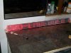
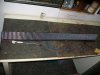
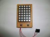
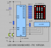
This project Named LED mini signboard.

Features

*User define message (String length = 30 letters including spaces)
*50 different characters = A-Z, 0-9 & special characters
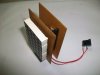
*Battery power operation 3.6V-4.8V

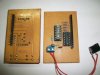
This is the smallest signboard I have ever made. The nice thing with this design is you can write your own message using its two buttons.

Saving is pretty simple

Press & hold the “Select” button at anytime. It will show you letter “A”. Now release the button. At each press the “Select” button it will shift to next character.
Press “Save” button to mark the selected letter. Likewise make a sentence by the two buttons & after completing press & hold the “Save” button for 4 seconds so it will save the whole sentence in the memory. Release the button now it will scroll the message nicely that you saved.

Supportable characters

Letters
A,B,C,D,E,F,G,H,I,J,K,L,M,N,O,P,Q,R,S,T,U,V,W,X,Y,Z SPACE

Numbers
1, 2, 3, 4, 5, 6, 7, 8, 9

Special
“/” “%” “Heart” “Face” “-““=” “Comma” “Arrow” “+” “:” “Dot” “(““)””Degree”

For additional details visit my blog https://gsmicro.blogspot.com/2008/12/mini-signboard.html
 

Attachments

  • Signboard Front.jpg
    Signboard Front.jpg
    50.5 KB · Views: 1,700
  • Signboard Side.jpg
    Signboard Side.jpg
    46.9 KB · Views: 1,202
  • Signboard Back.jpg
    Signboard Back.jpg
    51 KB · Views: 1,171
  • LED Mini Signboard.PNG
    LED Mini Signboard.PNG
    25 KB · Views: 3,847
  • Matrix.zip
    1.3 KB · Views: 1,151
Last edited:
Great project. I want to build it but can I substitute the uln 2003-darlington array with something else as I cant obtain one of these yet.
Thanks alot for letting us build it I can wait to test it.
 
Gayan, does your scrolling routine use any form of double / triple buffering? I had fiddled with a single character sign some time ago, and while scrolling static messages was easy, I ran into a mental road block in regards to code for scrolling dynamic messages, such as the time and date. Feature creep eventually killed my interest in the project - the trouble with adding too many bells and whistles.

**broken link removed**

blog post:
justDIY Project Log LED Sign has a purpose!
 
Hi justDIY there are five display column registers.But all the code is done with another five of working registers.At the end of the each display frame I'm loading working registers to the column registers.

Actually this project a bit hard & gets lengthier. The secret is withing the offset values to the table patterns :D

I see your project too that's bravo sir.
 
Last edited:
Gayan, can you put the .asm file on the forum as your website has absolutley no information on the LED Mini Signboard PIC 16F628A Project.
 
Hi Gayan,

What do you think about this design for Cathode row 5x7 displays? Perhaps a Clock/Calendar/Alarm/Timer/Sign project? And since the 74HC595 column drivers can 'sink' or 'source' you could use the same design for Anode row displays just by swapping out the N-FET 'sinking' row drivers with P-FET 'sourcing' drivers (and a minor software change).

Regards, Mike
k8lh-7x55-%C2%B5sign-concept-png.34823
 

Attachments

  • K8LH 7x55 µSign Concept.PNG
    K8LH 7x55 µSign Concept.PNG
    42.1 KB · Views: 15,680
Last edited:
Very nice sir.But I'm scared with your macMUX design its a bit complicated for me :D I'll show a similar design I recently did like your last diagram.But I did by cascading the shift registers using the QH' pins.
 
Last edited:
I would connect all the 595s the dame way you have it but use 1 more to control all the OE lines. And have all serial data on 1 pin. This way i can shift data to the 595 to select the first (last) 595 and then send that data...

let me make a schematic. It wont* be as pretty as mikes tho heh

EDIT:

Too lazy right now lol ill do it later on
 
Last edited:
Hi Gayan,

It's really very simple and it takes less time to send 56 bits of data for each row scan than it would for daisy-chained shift registers. If you're interested at all please let me know and I'll do a little write up to explain how it works. Once you understand how it works it's really quite intuitive.

Regards, Mike
 
Hi,
Connecting few Dot Matrix blocks and show some words or clock isn't that hard.
How about using dedicated display drivers. Like HOLTEK chips, MAX Ics & etc. It can reduce the MCU display driving load. That is a big saving right ! And also those chips hv some cool options like Display Dimming, Display Blinking, blah.blah....

Don't you think because of that saving we can do much more things with our MCUs ?

Plz correct me if im wrong.
Thanks
 
Last edited:
Mike

Here is another design of mine.The hardware is similar to your method with some minor changes in column driving side.

I cannot resist I want to show.

YouTube - Sign Large

Mike I like that "Micro Application Consultants" title
 

Attachments

  • Signboard1.jpg
    Signboard1.jpg
    54.2 KB · Views: 687
  • Signboard2.jpg
    Signboard2.jpg
    52 KB · Views: 575
Last edited:
Status
Not open for further replies.

Latest threads

New Articles From Microcontroller Tips

Back
Top