Continue to Site

Welcome to our site!

Electro Tech is an online community (with over 170,000 members) who enjoy talking about and building electronic circuits, projects and gadgets. To participate you need to register. Registration is free. Click here to register now.

  • Welcome to our site! Electro Tech is an online community (with over 170,000 members) who enjoy talking about and building electronic circuits, projects and gadgets. To participate you need to register. Registration is free. Click here to register now.

LED matrix with TLC5916INE4???

Status
Not open for further replies.

danjel

Member
I need to drive 32 leds, each needs about 20ma of current but my goal is to minimize the total current used. (using an arduino with atmega328 chip)

I am also avoiding the max7219 since it is an expensive chip (and I need to build a bunch of these).

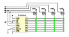
My plan originally was to just use 4 x TLC5916INE4 (each is an 8 bit shift register with constant currents sinks) and shift out the 32 led values.
I could also try pwm the Enable pin to reduce total current.

Plan B:
Create an LED matrix configuration of 4 rows x 8 columns.
The 8 columns could be sunk by the TLC5916INE4 so then I need to drive to drive the 4 rows. What is the best way to do this??
I can't do it straight off the arduino pins because each pin can only source 40ma.
Could I just use another shift register? If so which one could source enough current?
or make discrete current sources from transistors?
 
Lighting 32 LEDs to the brightness level of 20-ma "average" current is going to use the same power budget no matter how you design it. Consider your 1/4 duty cycle hardware design for example. If you want the brightness that 20-ma "average" current provides then you're going to set the constant current on the outputs of the TLC5916 to 80-ma "peak" current in order to provide 20-ma "average" current. So during each 8 LED column update you would be using 640-ma current (8 LEDs at 80-ma). You'll notice this is the same amount of current you would use to light all 32 LEDs with 20-ma current at 100% duty cycle.

As for driving columns on a 4x8 multiplexed design, just use four PNP or P-FET drivers as the high side (sourcing) drivers. If you use four pins to drive the PNP column drivers and a PWM pin to modulate the TLC5916 'OE' pin then you can retask those four column driver pins when PWM goes high (display off) at the beginning of each column scan interval as SDI and CLK pins to load the 8-bit shift register. After loading the shift register, setup the new column select bit pattern on the column pins before PWM goes low (display on). Varying the PWM duty cycle also provides PWM brightness control.

Good luck on your project.

Regards, Mike

tlc5916-png.34963
 

Attachments

  • TLC5916.PNG
    TLC5916.PNG
    13.3 KB · Views: 4,042
Last edited:
hi Mike,

My goal is to minimize total current draw to as low as possible. The leds are rated for a nominal 20mA but I should be able to drop that to 10-15mA... they do not have to be super bright. By cycling through the enable lines I am effectively pwm the entire display so depending on the duty cycle (I assume 25%) then the brightness will be lowered by that as well but now I understand from what you are saying that PWM does not reduce current draw on an individual led.

with the design you drew if I am cycling through 4 fets then at any time I only ever have a maximum of 8 leds on. If each led consumes 20mA current then the total current draw would be 160mA. I understand what you mean about pwm vs. perceived brightness... in my case I don't care if it is dimmer I just need to save as much mA as possible!

My other alternative is to use 4 SRs and but connect the enable pin of each one to uC pin and do the same thing (just load all 4 registers with my led states but then cycle through the enable pins at some rate).


btw, I am totally inexperienced using FETs. Is there a part number you would recommend? Do I need an resistors with it?

Also that is a clever idea to retask the col driver pins!
 
Last edited:
If you set the constant current for 20-ma and update the columns one at a time you'll have a 25% duty cycle and each LED will get about 5-ma "average current. This is plenty bright in most environments except in brightly sunlight lit rooms or outside.

I use SMT MOSFETs with logic-level-gates and very low Rds(on) for most of my projects; Vishay Si2323DS (P-FET) or Si2312BDS (N-FET).

Good luck with your project.

Kind regards, Mike
 
so I guess all I would need resistor from the gate of each fet to V+? what value is good?
 
Last edited:
thanks for all the help this has been great!!

one last question (given my ineptitude with fets)

Since I am using the FET as a switch does it matter if I use n-fet or p-fet? The only difference as far as I can tell would be the logic inversion for controlling it.
 
Last edited:
Hi danjel,

you can reduce LED current drastically by using low current LEDs. Their nominal forward current is 2mA (normal LED 20mA).

Boncuk
 
Hi danjel,

you can reduce LED current drastically by using low current LEDs. Their nominal forward current is 2mA (normal LED 20mA).

Boncuk

unfortunately in this situation I am limited by the leds that come packaged in Omron b3w-9 switches. It is the most compact illuminated tact switch I have found that contain red/green leds but unfortunately their nominal current rating is 20mA. I am going to experiment with them to see what current I can drop them down to and still be useable....
 
Last edited:
Status
Not open for further replies.

Latest threads

New Articles From Microcontroller Tips

Back
Top