Continue to Site

Welcome to our site!

Electro Tech is an online community (with over 170,000 members) who enjoy talking about and building electronic circuits, projects and gadgets. To participate you need to register. Registration is free. Click here to register now.

  • Welcome to our site! Electro Tech is an online community (with over 170,000 members) who enjoy talking about and building electronic circuits, projects and gadgets. To participate you need to register. Registration is free. Click here to register now.

LED driver

Status
Not open for further replies.

adinogcas

New Member
Hi guys,

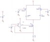
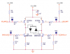
I need help on this circuit. This circuit is used to drive 2 LEDs. U1 and U2 are switch. Their inputs come from microcontroller (I use VDC to run simulation). They dont turn on/off at the same time, 1 is on and the other is off. The below half is a current sink to control intensity of the LEDs.

My problem is I can not completely turn OFF U1, U2. Is there any other way to turn them on/off completely?

Thanks,
 

Attachments

  • LED driver.jpg
    LED driver.jpg
    31.4 KB · Views: 1,231
The schematic looks ok. Are you sure you do not have the drain and source reversed in the actual circuit?
 
TP0610k are p-channel MOSFETs. To turn off, their gate should be at the same potential as their source which in this circuit is Vcc. They do not turn off when the gate is at ground.
 
I tried 5V power supply and this works fine. But 3.3V seems to be too small, I think I will need to change components, like PFET or LED. Do you guys have any suggestion of components that can properly operate at 3.3V?

Or should I change the circuit to use opamp in order to amplify the voltage between PFET and LED? I am really overwhelmed choosing components...new in this area :D
 
Anyone show me how to create PSPICE model for this LED: SML-LX2723SIC-TR. I use Cadence OrCad Pspice 16.0

Thanks in advance
 

Attachments

  • SML-LX2723SIC RED 350mA 630nm.pdf
    58.6 KB · Views: 348
Any one help me pls?

I can repeat what I am doing here:

I am trying to drive the LEDs with 3.3V power supply, 2 PFET, 1NFET and 1 opamp. 2 PFETs are ON/OFF switchs which are controlled by ucontroller (0-3.3V <-> On - OFF). The current through LED should be 100mA.

PFET: IRFD9220
NFET: 2N7000
Opamp: TLV262
LEDs: 1 RED and the other is IR.

If I use 5V power supply, the LEDs have enough power to run but the switches can only On/OFF at 0 and 3.3V(cant go to 5V). That means it can not go OFF completely which is not desired.

If I use 3.3V power supply, the LEDs do not have enough power to run, which I dont know why...LEDs forward voltage are 2V (Typical - from datasheet). When I turn switch (1 on and the other off) on (Gate to 0V), I expect the anode of LED has around 5V and cathod has around 3V. But when I measure it, it shows only 1.6V at anode (and cathod is 0V) so there is only 1.6V drop across the LED. Why is that? Why there is so much voltage drop across the PFET? 5-1.6=3.4V??? Where am I wrong?

Please help me
 
Last edited:
Ok, I think of something. When 1 switch(SW) is on, the NFET is also on (to drive the current throught LED) which means Vd of NFET should be 0V. But the forward voltage is only 2V so ... only 2 V drop across the LED and the rest will drop across the PFET (switch), is that correct?

If that's correct should I put a resistor between PFET and LED to maintain the correct voltage drop in PFET and the LED? Or how can I solve this problem? I think 3.3V is enough to run this circuit, is it correct?

I really appreciate any help in this problem
 
The LED can have a forward voltage up to 2.9V, which leaves very little for control circuits.
The 2N7000 does not begin to have reasonable ON resistance until its gate is almost 4V.
The IRFD9220 does not begin to have reasonable ON resistance until its gate is almost 4V.

To work at 3.3V, you must change all of the components.
 
If your Microcontroller is a PIC, you could use one with 2 CCP pins connected to the bases of 2 NPN transistors. Set the CCP pin for PWM to control the brightness. For switching On and Off, set/clear the TRIS bit for the CCP pins. You would then get PWM, and independant switching of the 2 Leds with only 2 transistors.
Any thoughts on this??

Jim
 
Thank you for your replies. I changed the circuit by taking out 2 PFETs which is switch. Then the circuit only has Opamp, NFET and LEDs. Can anyone verify this circuit?

I/O ports are switches to provide 0V or 3.3V and the half lower is current sink. This circuit does not turn both LEDs at the same time, it has 3 phases: Led1 on, Led2 off, vice versa and both off. So I think 1 current sink is enough to drive both LEDs.

However, in the same application, I saw someone use H-bridge (4 BJT transistors) to drive the LEDs. Could any one tell me the different between my circuit and that H-bridge? Why do they need H-bridge to drive the circuit while not hook LEDs (with current sink) directly to ucontroller to turn ON/OFF?
 

Attachments

  • H-bridge circuit.png
    H-bridge circuit.png
    93.9 KB · Views: 2,490
  • circuit1.jpg
    circuit1.jpg
    19.4 KB · Views: 953
Thank you for your replies. I changed the circuit by taking out 2 PFETs which is switch. Then the circuit only has Opamp, NFET and LEDs. Can anyone verify this circuit?

I/O ports are switches to provide 0V or 3.3V and the half lower is current sink. This circuit does not turn both LEDs at the same time, it has 3 phases: Led1 on, Led2 off, vice versa and both off. So I think 1 current sink is enough to drive both LEDs.

However, in the same application, I saw someone use H-bridge (4 BJT transistors) to drive the LEDs. Could any one tell me the different between my circuit and that H-bridge? Why do they need H-bridge to drive the circuit while not hook LEDs (with current sink) directly to ucontroller to turn ON/OFF?

From your posts above, you say that you want to drive the Leds @ 100mA? Although you are sinking via a Fet, can't draw 100mA directly from a Microcontroller I/O pin.
 
Status
Not open for further replies.

Latest threads

New Articles From Microcontroller Tips

Back
Top