Continue to Site

Welcome to our site!

Electro Tech is an online community (with over 170,000 members) who enjoy talking about and building electronic circuits, projects and gadgets. To participate you need to register. Registration is free. Click here to register now.

  • Welcome to our site! Electro Tech is an online community (with over 170,000 members) who enjoy talking about and building electronic circuits, projects and gadgets. To participate you need to register. Registration is free. Click here to register now.

LED Dimming/Brightening Circuit?

Status
Not open for further replies.

Silenced

New Member
Hi all, I'm new here, just because I need some help with a circuit I'd like to design

I would like to design a circuit that will let me dim or brighten some LED's, which is simple enough I'm guessing, power, potentiometer and some LEDs.

But this is slightly different

I will be making this be powered off 12V from a Molex connecter in a computer, in turn it will power some LEDs inside a fan casing.

Once again, sounds simple but these LEDs are Full Spectrum LED's, which means they have a Blue, Red and Green light in them.

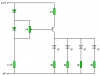
So I would like it so I could change the amount of blue, red and green turned on in the LEDs using 3 potentiometers for each colour.

Another problem it seems it that I will want to change the amount of LEDs according to the number of fans in my PC.

Any help on how to do this?
 
Well, the simplest solution is to just connect a variable resistor and fixed resistor in series with the LED but it isn't ideal because it won't give you that much of an adjustment range.

A better solution is to use a constant current source.

The circuit attached will work from from 12V but it's more efficient to use the 5V supply.

If you're using a RGB LED it will need to be common anode, otherwise you need to reverse the diode and supply polarities and change the transistor to PNP.
 

Attachments

  • LED Dimmer.GIF
    LED Dimmer.GIF
    2.7 KB · Views: 1,684
Last edited:
Thanks for your response Hero999.

I currently have Common Cathode LEDs as the Common Anode ones wouldn't seem to light when I tried to light all three at the same time.

I'd also like to mention the circuit would have 4+ LEDs hooked into it, as I would be putting 4 LEDs per fan, with up to 4 fans. So the circuit needs to be very dynamic :/
 
Here's how I'd do it.

You'll need one of these circuits for each colour LED, one for red, green and blue.

Wire all the cathodes to 0V.

Note that this circuit is a constant current source which will give about 60mA so don't use it for any less than three LEDs and if there are more than six LEDs, the brightness will be drastically reduced unless you reduce the current sense resistor.
 

Attachments

  • 4 LED dimmer..png
    4 LED dimmer..png
    866 bytes · Views: 1,119
Is there anyway I could make it variable current source? Just because I might add in or take out LEDs at my leisure, so making a new circuit wouldn't be too handy
 
You can make it variable voltage but it's not idea.

If you configure an LM317 with a variable voltage of 1.25 to 9V and use a fixed value resistor for each LED it will also work but it won't be ideal.
 
Status
Not open for further replies.

Latest threads

Back
Top