helo..
i would like to ask whether i am suppose to find individual values first,
then put everything together?
also some notations of values like RB2 is not on the schematic.
thx. looking forward to ur reply.
Hi,
If you looked at my schematic and try to figure out the values,and then build it, probably would be difficult to do.
Mainly because you need to take preliminary measurements.
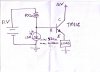
RB2 is labeled as the resistor (LSR) from base to pos. supply on the emitter follower stage.
I hope that answered your questions......However if you want to you could read on.
I'll try to explain the best I can of what designing this circuit entailed.
Since my components are different than yours (LDR, led ect...) means there has to be building and test measurements in the process.
It's good to have a breadboard, multimeter, and a resistor substitution box, handy in designing circuits. as well as a calculator, and a notepad for recording data.
Seeing it is a homework assignment I am limited to how much detail I can give in this design.
That's why this is presented so vagouly.
I'm presenting this in a way that can be beneficial as a learning experiance in design work.
(What I'm trying to drive home is gather as much data from your circuit as it is progressing, and question why voltages are this and that, and have a thoro understanding why your measurements are as such.)
Now the procedures.
1. To drive the led at it's maximin brightness could be done through a emitter follower.
however a more direct positive result would be to drive it through it's own series dropping resistor.
So hook your led from ground through a high say, 2K series resistor, to the battery positive. Observe the brightness of LED. Then begin to decrease the resistor until you get a led brightness your satisfied with. Then take some measurements across the led. and across the rersitor, mark these measurements down, in your design notebook. Now you have determined the full brightness of your led.
As before, in your circuit you had no controle over the brightness of the led, the circuit controled the outcome. But since your the designer you can controle the led the way yoyu want it to work. (Don;t let your design controle you, but you take controle of your design, you make it work the way you want it to)
2. Now we want to turn the led off, while it is still hooked up in this config. so how would you do it, well first draw it up in your notepad, hint: if I gave you 1 resistor at this point and you have it in your hand where would you hook it up at to turn the led full off. answer: Across the led, why?... Now using a resistor sub box hook up a resistor in parrallell across the led, begin lowering this resistance until your led is off, or barely lit.
Take measurement across series resistance value, and calculate current through it.(that will be your collector current (Ic) for the next step) Also you will need to know the voltage from ground to the junction between the led and the series resistor. Because that is the turn off voltage needed for this output.(Vc) record it. youll need it in step 5.
Also measure the value of your (LDR) under full lighting conditions.(needed in step 10.)
3. Now draw a schem. of a transistor inverter. Lable the series resistor as RC.
Choose a Vce of what you want it to be ,and then calculate the emitter resistance RE needed to deliver the current (Ic) calculated in step 2 through this series resistor.
4. Now calculate the Vb and choose a resistor RB to be 10-20 times larger than RE.
calculate the Rb2 value needed to bias the transistor so Ic is at around the value calculated in step 2. Rb2 is the bias resistor from base to positive supply.
5. Breadboard the circuit and adjust values until you get Vc. as you meaasured before. make sure led is not lit. Now temp. remove RB2 (top resistor) make sure the led is on.
The inverter is working properly.
From here I have copied and pasted from my original post starting at step 9.
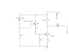
step 9. Calculate your current flow through the base resistor to ground, on your inverter circuit from step 4. (what you will eventually do is replace RB2, with this emitter follower).
step 10. Now using this current value calculate the volt. drop across the RE of this emitter follower. So now you have the RE and Ic calculated for this emitter follower. Now on this schem. lable the base res. that connects to the positive VCC, as the value of your LDR you measured from step 2
step 11. Calculate the RB1 base to ground res. needed to complete the bias of this emitter follower circuit. Build this circuit temporarily connecting the RE to ground and take measurements and adjust only the RB1 value until you get the Ic calculated for this stage.
step 12. connect the emitter follower in place of the RB2 resistor in your inverter stage, then adjust values only on the RB1 res. (base to ground) of the emitter follower until the Vc of the inverter matchs the Vc measured from step. 2.
When your Vc. is correct than finally remove the RB2 (base to Vcc) res. from the emitter follower, and replace it with your LSR and the led should be off on bright light conditions.
Then as you slowly move your hand above the LSR the led should come on gradually in accordance to the amount of shadowing above it. As I move the board away from light source the led responds in a very linear way it gradually changes according to the amount of lighting on the cds cell.
Again I must refrain from giving you the answers to the values as this is a homnework assignment, but I'm trying to get you to look at this circuit from a thoro understanding of what it's doing and why it works the way it does.
Which means is if someone were to say to you why couldn't you use this resistor instead bla bla bla...That you could give a logical answer to why it would or would not work.
")