Hi,
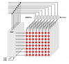
I have mastered a 8x8 LED matrix using two shift registers, and now i want to add another dimension to it. I have thought long and hard about it and have done a fair amount of research. I plan to make a 64x8 array. The illustration below I made a while ago, but helps understand what im thinking.
**broken link removed**
This design will use 9 shift registers, 8 to make the 64 columns, and 1 to make the 8 rows. This is based off the advice given to me from someone else who had successfully used this design.
However, it's not the design that puzzles me, but how i mange the current to stay within the limits of the ICs and the LEDs. I don't understand what i have to put between the shift registers and LEDs. I understand the need for 220-ohm resistors, but i have read in some places i need transistors to take the large load of the ICs when dealing with matrices the size of mine. I have seen a few different ways, from simply having lots of transistors to a 'Darlington Transistor Arrays' or LED Drivers. Futhermore, **broken link removed**, a commercial 4x4x4 tri-colour cube, clearly doesnt have a resistor on every LED, which i thought was a requirement.
I have found no definitive answer for what i place between the Shift Registers and the matrix, and with my lack of experience, i have just got confused. Does anyone know how i should manage the currents as to not blow the ICs or LEDs? (And idealy, save me the need to solder 64 transitors and/or resistors, as done in the Hypnocube)
Kind Regards,
Mitch