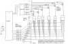
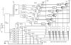
I'm building a digital clock using LED's in a 7 segment pattern. Each segment has around 35 LEDs and the height of a complete display is around 12 inches. i'm using two displays each, for hours, minutes and seconds. A PIC 16f877 sets the number to be displayed and a 74HC238 demultiplexer selects each display. Only one display is on at any given time, to save power. Problem is the LEDs are not bright enough. I tried using transistors to increase the current but it doesn't help, because its switching between each display so fast. Please help!!!
Continue to Site