Continue to Site

Welcome to our site!

Electro Tech is an online community (with over 170,000 members) who enjoy talking about and building electronic circuits, projects and gadgets. To participate you need to register. Registration is free. Click here to register now.

  • Welcome to our site! Electro Tech is an online community (with over 170,000 members) who enjoy talking about and building electronic circuits, projects and gadgets. To participate you need to register. Registration is free. Click here to register now.

LED circuit

Status
Not open for further replies.

lsmall

New Member
Hi, please forgive my ignorance, my knowledge is limited for this stuff.

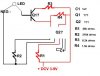
I have made the circuit attached here. It consists of 3 parallel LEDs each with a resistor in series. The resistors are 330ohm and the specs on the LEDs are If mA: 20 (max.), Vf: 3.7 (volts typ.), Vf: 4.5 (volts max.)
The circuit is powered by a variable DC supply.

I'm not sure how to figure in the impedance of the LEDs into my calculations. I have estimated the impedance based on the above data, but I don't think I have it right. Somewhere between 185-550 ohms?

I have calculated that I can safely use this circuit up to about 9VDC. I am currently running it on 4.5VDC and it works fine.

Can anyone verify this for me?

Thanks,
lsmall
 

Attachments

  • circuit_181.jpg
    circuit_181.jpg
    14.4 KB · Views: 875
cct fine except for the batter is the wrong way up
 
lsmall said:
I'm not sure how to figure in the impedance of the LEDs into my calculations. I have estimated the impedance based on the above data, but I don't think I have it right. Somewhere between 185-550 ohms?

LEDs don't really resolve down to an impedance due to their extremely nonlinear i/v curves. What do you want to use the figure for? We can calculate the current...
 
Basically, I'm using this for an aquarium nightlight to simulate very faint moonlight.

I'm using a variable DC supply rated to 300mA.

I'm trying to figure how high I can increase the voltage without frying the LEDs.

So if I can disregard the resistance of the LEDs, the total resistance of the circuit is 110 ohms-correct me if I'm wrong.

At 4.5v, there would be 40mA total in the circuit and 13.3mA running through each resistor/LED unit. Is that right? If the LEDs resistance is negligible then how do you get a voltage dropoff across the LED?

So can I safely increase to 6v? That should give me 18mA to each LED, but what's the vf of the LED if we can't figure out its resistance?

Thanks
 
yes 6V is the maximum voltage i would use..
LEDs are diodes it is the forward current through them that you can't exceed, without burning them out..
 
LEDs only change their voltage a little bit when you increase the current.

First you need to know how much current your LEDs can take in the long term. You can really only be sure by looking at their spec sheet. Power LEDs you can easily overdrive by 2x, 10x, and they'll last for hours, days, or longer but slowly degrade over that time. What I'm saying is it's hard to find out what they can take by experimenting with them.

As far as the resistor value goes, unless you have a specifications to show how much the LED voltage changes with a change in current, just start by assuming it won't change. So if you halve the resistor value, the LED current will double. In reality, the LED voltage will go up some, lowering the current a bit below that prediction. The intensity of that effect on the new current will vary depending on how much of the source voltage was dropped across the resistors to begin with.
 
Just assume the voltage drop across LED is constant ( around 1.0V), similiar with diode.
Read from the spec that how much current is required (roughly 3-5mA), and calculate the resistor.

However, there is alternative. Forgot whatever I mention above.
Just connect any resistance starting from , lets say 10K, and observe the light intensity. If it is too dim, replace the resistor value. Keep using low resistance until u are happy with the LED brigthness. I usually use 1K for 5V supply.
 
Status
Not open for further replies.

New Articles From Microcontroller Tips

Back
Top