Continue to Site

Welcome to our site!

Electro Tech is an online community (with over 170,000 members) who enjoy talking about and building electronic circuits, projects and gadgets. To participate you need to register. Registration is free. Click here to register now.

  • Welcome to our site! Electro Tech is an online community (with over 170,000 members) who enjoy talking about and building electronic circuits, projects and gadgets. To participate you need to register. Registration is free. Click here to register now.

LED Circuit

Status
Not open for further replies.

xXAxHillbillyXx

New Member
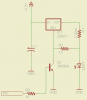
I am makeing a circuit that controls the brightness of high power leds through PWM, I have come up with this circuit to power the leds and to let the arduino PWM the grounds... any suggestions that i need to do to it? and ideas what transistor i need to use? i am pretty sure my math is right as to what the current values should be
led1: 625mA
led2: 625mA
led3: 625mA
led4, 5, 6: 312mA

**broken link removed**
 
Not a good way of doing it. First, the NPNs are sinking ~0.6A, so they will need a base current of ~60mA, which the uC cannot source. Also, the Dissipation in the LM317s will be huge; they will need to be on huge heatsinks...

I would use an NFET for the switch. By moving the current-limiting resistor into the source, the NFET can do double-duty by limiting the LED current at the same time.

What is the Vdd for the uC? What is the forward voltage for the LEDs at 0.6A? At 0.3A?
 
Last edited:
You could instead place a resistor between the ADJ and R1, then use a small transistor to pull the ADJ pin to ground.
Doing so would drop the output to 1.2v. effectively turning it off.

ledcc-png.46064


Also, as MikeMl has stated, the regulators will dissipate a lot of heat.
 

Attachments

  • LEDCC.png
    LEDCC.png
    8 KB · Views: 582
Not a good way of doing it. First, the NPNs are sinking ~0.6A, so they will need a base current of ~60mA, which the uC cannot source. Also, the Dissipation in the LM317s will be huge; they will need to be on huge heatsinks...

I would use an NFET for the switch. By moving the current-limiting resistor into the source, the NFET can do double-duty by limiting the LED current at the same time.

What is the Vdd for the uC? What is the forward voltage for the LEDs at 0.6A? At 0.3A?

ok so what your saying is to get rid of the 317's all together put a series resistor inline with the 12v source and put the nfet between the led and ground? Like this? If it is like this what nfet would you recommend or will any one do?
**broken link removed**
 

Attachments

  • schem2.sch
    65.9 KB · Views: 134
Not quite. I would make the NFET a "constant-current sink" by putting a suitable resistor in the source lead.

You didn't answer the questions I asked:

What is the Vdd for the uC? What is the forward voltage for the LEDs at 0.6A? At 0.3A?
 
Not quite. I would make the NFET a "constant-current sink" by putting a suitable resistor in the source lead.

You didn't answer the questions I asked:

What is the Vdd for the uC? What is the forward voltage for the LEDs at 0.6A? At 0.3A?

The uC's vdd is 5v, as for led's 1-3 the forward voltage is given for 0.7A so so i am going to assume that is close enough.
led1,red= 3.6Vf
led2,green= 3.4Vf
led3, royal blue= 3.4Vf

led's 4-6 are white high power leds and there ratings are
led4-6, white= 3.4Vf

**broken link removed**
data sheet for led's 4-6
data sheet for the uC
 
You might look at the NTD4856. The price is right and you wouldn't need a heatsink. It will also switch at 5 volts if that is the micro output. Don't forget to calculate the power in the resistor and the LED. The downside is it is not constant current.
 
Status
Not open for further replies.

Latest threads

New Articles From Microcontroller Tips

Back
Top