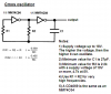
First, I didn't design this circuit.
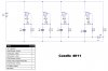
Second, I used 4011 NAND gates insted of 4093 (what I had)...
I simulated this with Livewire, works. And then built it on a proto board, which doesn't. The LED stays on, no flicker or fade. Hooked up my cheap hand-held scope, each gate seems to oscilate, but not all together, or at the LED. Perhaps I need to isolate the NAND outputs with diodes (1N914).