info from:
https://www.electro-tech-online.com/custompdfs/2003/10/39340011.pdf
Detection of START and STOP conditions by devices
connected to the bus is easy if they incorporate the
necessary interfacing hardware. However,
microcontrollers with no such interface have to sample the
SDA line at least twice per clock period to sense the
transition.
i dun quite understand this statement
i think im getting the hang of I²C already
So can you see for me whether my steps of the program is correct?
Here are the steps:
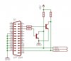
1) Check whether bus is free => check SCL(11) and SDA(12) for high
If free, set SCL(3) high and set SDA(2)high to low
2) Provide clock signal to SCL(3)
check SCL(11),
SCL(11) = low, Delay
SCL(11)= high, Continue with A
above 3 sentance is to check whether slave has completed its operation.
Will the device auto delay or i need to add the 3 statements?
A)Set SCL(3) low
B)Set SDA(2) high/low
C)Delay
D)Set SCL(3) high
E)Delay
go back to A until 8 bit data and ack bit is sent.
3)Check for acknowledgement SDA(12),
if high => Stop program
if low => continue sending next 8 bit data
4) To stop after 8 bit transfer, set SDA(2) from low to high when SCL(11) is high.
hope this is correct..
also if i only use one master directly to the slave device, do i need to send the binary address? if yes, how would i get the binary address of the slave device.
thx everyone.