Continue to Site

Welcome to our site!

Electro Tech is an online community (with over 170,000 members) who enjoy talking about and building electronic circuits, projects and gadgets. To participate you need to register. Registration is free. Click here to register now.

  • Welcome to our site! Electro Tech is an online community (with over 170,000 members) who enjoy talking about and building electronic circuits, projects and gadgets. To participate you need to register. Registration is free. Click here to register now.

LCD Module help

Status
Not open for further replies.

farso

New Member
Hi

A little background info for you...

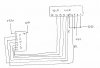
I am using a Ez430-F2013 to try and drive a 16x2 LCD. I know that the MSP430's run off ~3.3v so I have a 7805 dropping a 9v battery down to 5v to drive the LCD.

The problem...

To begin with I was using the wrong datasheet (doh!) and hence was wiring up wrong. Since then I have found the error in my ways and corrected the circuit, but still no reaction from the display other than the backlight turning on.

So...

I was wondering if (with 5v for no more than 60s on the wrong pins) there could be enough damage to the lcd to stop it working?

Further reading
https://www.electro-tech-online.com/custompdfs/2009/08/0900766b806dda15.pdf

Datasheet for the LCD module.

Thanks in advance for any help!
 
I was helping my brother hook one of these up today and he did exactly the same (swapped all the pins, connecting VCC and VO to the data pins). There was no damage to the display, but you can never know. You can simulate your code using Proteus if you can obtain a trial license - that will eliminate any software issues.

Other than that, post your schematic and code we we can try to take a look.
 
Thanks for the quick reply. I cant remember which pins were reversed, Im thinking that some of the data pins were stuck high and others grounded, but I cant be certain.

I do have access to proteus, but didnt know that it had the MSP430 chips available on it? Would be great to try it out like that if it does.

If your interested in the circuit, I borrowed the code from this location: Calculator Project Guided Tutorial Leah Shanker - All seems to be working to me.

Am I correct in thinking that after LCD has initialzed then there should be some noticable difference to its off state?

Thanks
 
Im not certain which lines got reversed as I was looking at a different datasheet, but I dont think that I reversed Vdd and Vss at any point.

Does proteus simulate the MSP430 range? I do have access to it but have not used it as i didnt think it did.

After powering up the LCD is there an easy way to tell that it is damaged or not without sending inststructions? Is there also a noticable difference when the screen itself is powered up to when it is not and just the backlight functioning?

Thanks
 
Unfortunately it doesn't, but since the LCDs are operated via GPIOs it shouldn't be too hard to simulate using a PIC (which proteus does support) - just to make sure you are sending the commands right.

Visual indications - i don't know if all LCDs behave the same way. The one i used today showed slight shadowing of the first row which increased as i upped the voltage on VO (before any commands sent).

Again, if you post your code and schematics maybe we can point glaring errors.
 
Hi. In order to test the lcd I have been using pre-written code by two other people (neither of which has worked so far) I was aiming to get it running as a test then start coding my own set of instructions.

Calculator Project Guided Tutorial Leah Shanker

and

RANJIT PURI - How to MSP430 ?

The code and pin connections are used there, but modified for my lcd display as pin positions are pretty different (hence wiring up wrong)

Might just get another LCD display and give it a try. Anyone know where to get one pretty cheap in the UK? This one cost me just over £5 from RS with my student discount.

Thanks
 
After a further hour of tests Ive given in to the thought that Ive broken the LCD, so have ordered some more.

If anyone is interested, someone is selling 10x 16x2 LCD's without backlight for £10 + £2P&P... Just ordered mine and it still says over 10 lots available.
 
Hi to anyone still reading what I have to say... Once again one more question.

I have wired up the LCD and it does appear to power up with my 7805 circuit, however it does not seem to want to accept logic inputs from the F2013.

So to ask the experts...
1. Does a 5v LCD need 5v data lines?
2. Should I put some pull down resistors on the outputs? Would this help?

Thanks, its frustrating me a little now!

PS. I dont have a datasheet, but it runs off the HD44780 chipset.
 
Have you got the contrast voltage set for the lcd? If its set too high it would give the symptom of being dead..

I found the first time I used an lcd, I thought it was dead...Turned out that the contrast voltage needs to be turned rifgt down to zero volts almost...in fact even a negative voltage might have helped.
 
LCD contrast is correct I think, when the LCD turns on it shows one line light and the other dark, I'm assuming this is some sort of startup test? As I mentioned before, I'm sure its powered up ok... just wont take data and give me a blinking cursor!

Ive tried manually setting DB0 - DB4 at 5v and clocking E, no result

I have also tried with microcontroller doing DB5, E, 0, E, 0, E, DB4-DB7, E. ( I think this is the same as above but 4bit mode?)
 
Hi, thanks for the reply.

R/W is grounded, I assumed a problem with the uc, so tried to connect DB0-DB3 to +5v, then touch +5v to the E, but no response. Is this normal also? Tried looking on the internet for stuff like this, but all info assumes that you can get them running ok!
 
Hi. Thanks for all your help, it is much appreciated.

The basic code follows.. just to try and get the lcd initialized!
Code:
#include <msp430x20x3.h>
#define E BIT0
#define RS BIT1
#define DB4 BIT2
#define DB5 BIT3
#define DB6 BIT4
#define DB6 BIT5


void wait(void)		// simple function creates delay
{
   int i, q; 
   for (i = 0; i < 100; i++);
   {
   	q = 10*100;		// slow it down a little
   }
}

void enable(void)
{
	wait();
	P1OUT |= E;		// enable E
	wait();
	P1OUT ^= E;		// disable E
	wait();
}	


int main(void)
{
P1DIR = 0xff;		// all ports facing out
P1OUT = 0;			// make sure everything is off
wait();
P1OUT |= DB5;		// set 4bit mode
enable();
P1OUT = 0;			// first nibble
enable();
P1OUT |= ( DB4 | DB5 | DB6 | DB7 );		// clear screen, blink cursor
enable();
__low_power_mode_4();		// dont move any further
return 0;
}

The circuit should explain itself from how the code is written, but it is attached anyway.

Regarding the parallel port, its a good idea, but Im on one of those laptops that has got rid of every port aside from usb, hdmi, esata and all other stuff that I dont need :confused:

Once again, thanks for all the help that your offering.
 

Attachments

  • gareth 2.jpg
    gareth 2.jpg
    58.5 KB · Views: 184
Some notes:

1) There is no way for me to see how P1 is connected to the LCD (which bits are mapped to which data lines). According to your code, the MSb (bit 7) is connected to DB7, bit 6 to DB6 and so forth. If this is not the case you are not connected properly. To verify, break after: P1OUT |= DB5; and test the data lines. The correct values should be: DB7: 0 DB6: 0 DB5: 1 DB4: 0
2) I don't know if your startup sequence is wrong, but it's different than mine. Try to following:

// initial function set
DB7 : DB4 = 0010
Pulse Enable
Wait 50ms

// resend function set w/params (5x7 font, 2 lines)
DB7 : DB4 = 0010
Pulse Enable
DB7 : DB4 = 1000
Pulse Enable
Wait 2ms

// blink cursor, display on
DB7 : DB4 = 0000
Pulse Enable
DB7 : DB4 = 1111
Pulse Enable
Wait 2ms

At this point you should see a blinking cursor. Check my drivers page for an HD44780 driver which should show you how to continue the initialization (not much further).

3) Your contrast pin (3) is grounded. This will set the contrast to 0 and you will see nothing. Connect this to a variable resistor.
4) I think the enable pulse has a max value. Check the data sheet and see that you are within spec. I pulse it for about ~5uS i think.
 
Status
Not open for further replies.

Latest threads

New Articles From Microcontroller Tips

Back
Top