Continue to Site

Welcome to our site!

Electro Tech is an online community (with over 170,000 members) who enjoy talking about and building electronic circuits, projects and gadgets. To participate you need to register. Registration is free. Click here to register now.

  • Welcome to our site! Electro Tech is an online community (with over 170,000 members) who enjoy talking about and building electronic circuits, projects and gadgets. To participate you need to register. Registration is free. Click here to register now.

LCD display value no response??

Status
Not open for further replies.

haowhaow

New Member
im newbie in programming.....im using MPlab and HI tech compiler to simulate my project.....
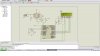
i would like to create a temperature measurement device by using thermocouple....
the problem is my lcd display no response (stay at 000) even i have changing my thermocouple value....

HOpe that anyone here can help me to figure out what happened..appreciated it!!


here is my coding.......


#include <htc.h>
#include <math.h>

#include "lcd.h"

#pragma config WDT = OFF
#pragma LVP = OFF
#pragma OSC = INTIO67


//Simple Delay Routine
void Wait(unsigned int delay)
{
for(;delay;delay--)
__delay_us(100);
}


//Function to Initialise the ADC Module
void ADCInit()
{
//We use default value for +/- Vref
//VCFG0=0,VCFG1=0
//That means +Vref = Vdd (5v) and -Vref=GEN

//Port Configuration
//We also use default value here too
//All ANx channels are Analog

/*
ADCON2

*ADC Result Right Justified.
*Acquisition Time = 2TAD
*Conversion Clock = 32 Tosc
*/

ADCON2=0b10001010;
}

//Function to Read given ADC channel (0-13)
unsigned int ADCRead(unsigned char ch)
{

if(ch>13) return 0; //Invalid Channel

ADCON0=0x00;

ADCON0=(ch<<2); //Select ADC Channel

ADON=1; //switch on the adc module

GODONE=1;//Start conversion

while(GODONE); //wait for the conversion to finish

ADON=0; //switch off adc

return ADRES;

}
void main()
{
//Let the LCD Module start up
Wait(100);

//Initialize the LCD Module
LCDInit(LS_BLINK);

//Initialize the ADC Module
ADCInit();

//Clear the Module
LCDClear();

//Write a string at current cursor pos
LCDWriteString("Temperature:");
LCDWriteStringXY(4,1,"Degree C");


while(1)
{
unsigned int val;
unsigned int t; //Temperature

val=ADCRead(0); //Read Channel 0
//voltage= ((val)/1100)*5;
//The above formula give voltage in Volts, to get Voltage in mili Volts (mV) we must multiply it with 1000, so

//voltage=((val)/1100)*5*1000); //Voltage is in mV
//since (1/220)mV = 1 degree, to get temperature we must divide it by 1/220, so

//t=((val)/1100)*5*1000*220); //t is in degree centigrade
//simplifying further we get

//t=((val/1100)*1100000);
//t=(val*1000);
//we round off this value, so

t=round(val*1000);

LCDWriteIntXY(0,1,t,3);//Prit IT!


Wait(1000);

}
}
 
Last edited:
What chip your using would be nice to Know

ADCON0=0b00001011//ADCON0: A/D CONTROL REGISTER Analog Channel Select bits

not this ADCON0=(ch<<2); //Select ADC Channel

And not knowing what chip your using but I would say you need to added this too
ADCON1=0b00001101 //A/D Port Configuration Control bits Voltage Reference Configuration bit

Set them wrong and you'll get no reading

VCFG1: Voltage Reference Configuration bit (VREF- source)
1 = VREF- (AN2)
0 = VSS

So you would get a 0 on the LCD


ohhhh......im using PIC18f4520....with this chip i need to set like what u have mention??? really appreciated ur helps.....
 
hi be80be....

i have been try what u have shown me as above....but my display still the same..what can i try nexT?? OR here i attach my schematic.....can u help me to figure out is there any mistake??
 

Attachments

  • 1.JPG
    1.JPG
    137.2 KB · Views: 193
re-post your code so we can see what you did

ADCON1=0b00001110 this is what you need. Not ADCON1=0b00001101
 
Last edited:
re-post your code so we can see what you did

ADCON1=0b00001110 this is what you need. Not ADCON1=0b00001101


#include <htc.h>
#include <math.h>

#include "lcd.h"

#pragma config WDT = OFF
#pragma LVP = OFF
#pragma OSC = INTIO67

//Simple Delay Routine
void Wait(unsigned int delay)
{
for(;delay;delay--)
__delay_us(100);
}


//Function to Initialise the ADC Module
void ADCInit()
{
//We use default value for +/- Vref
//VCFG0=0,VCFG1=0
//That means +Vref = Vdd (5v) and -Vref=GEN

//Port Configuration
//We also use default value here too
//All ANx channels are Analog

/*
ADCON2

*ADC Result Right Justified.
*Acquisition Time = 2TAD
*Conversion Clock = 32 Tosc
*/

ADCON2=0b10001010;
}

//Function to Read given ADC channel (0-13)
unsigned int ADCRead(unsigned char ch)
{

if(ch>13) return 0; //Invalid Channel

ADCON0=0b00001011;

ADCON1=0b00001110;

ADON=1; //switch on the adc module

GODONE=1;//Start conversion

while(GODONE); //wait for the conversion to finish

ADON=0; //switch off adc

return ADRES;

}
void main()
{
//Let the LCD Module start up
Wait(100);

//Initialize the LCD Module
LCDInit(LS_BLINK);

//Initialize the ADC Module
ADCInit();

//Clear the Module
LCDClear();

//Write a string at current cursor pos
LCDWriteString("Temperature:");
LCDWriteStringXY(4,1,"Degree C");

while(1)
{
unsigned int val;
unsigned int t; //Temperature

val=ADCRead(0); //Read Channel 0
//voltage= ((val)/1100)*5;
//The above formula give voltage in Volts, to get Voltage in mili Volts (mV) we must multiply it with 1000, so

//voltage=((val)/1100)*5*1000); //Voltage is in mV
//since (1/220)mV = 1 degree, to get temperature we must divide it by 1/220, so

//t=((val)/1100)*5*1000*220); //t is in degree centigrade
//simplifying further we get

//t=((val/1100)*1100000);
//t=(val*1000);
//we round off this value, so

t=round(val*1000);

LCDWriteIntXY(0,1,t,3);//Prit IT!


Wait(1000);

}
}


Ohh ya...sorry for asking how to set the voltage reference configuration bit VCFG0, VCFG1 ???
 
bit 5 VCFG1: Voltage Reference Configuration bit (VREF- source)
1 = VREF- (AN2)
0 = VSS
bit 4 VCFG0: Voltage Reference Configuration bit (VREF+ source)
1 = VREF+ (AN3)
0 = VDD

Yon set bits 5 and 4 of ADCON1=0b00001110;
 
bit 5 VCFG1: Voltage Reference Configuration bit (VREF- source)
1 = VREF- (AN2)
0 = VSS
bit 4 VCFG0: Voltage Reference Configuration bit (VREF+ source)
1 = VREF+ (AN3)
0 = VDD

Yon set bits 5 and 4 of ADCON1=0b00001110;

ya i know bit 5 is VCFG1 and bit 4 for VCFG0 ....but the problem is i dunno how to write it??sorry im noob....

izzit u mean set ADCON1 = 0b00101110??
 
Last edited:
Bit 7 = 0
bit 6 = 0
bit 5 = 0 for VSS 1 VREF-(AN2)
bit 4 = 0 for VDD 1 VREF+(AN3)
bit 3 = 1 \
bit 2 = 1 \
bit 1 = 1 / these set the pin you want to use
bit 0 = 0 /

ADCON1 = 0b00001110

Just like this
 
Bit 7 = 0
bit 6 = 0
bit 5 = 0 for VSS 1 VREF-(AN2)
bit 4 = 0 for VDD 1 VREF+(AN3)
bit 3 = 1 \
bit 2 = 1 \
bit 1 = 1 / these set the pin you want to use
bit 0 = 0 /

ADCON1 = 0b00001110

Just like this

#include <htc.h>
#include <math.h>

#include "lcd.h"

#pragma config WDT = OFF
#pragma LVP = OFF
#pragma OSC = INTIO67

//Simple Delay Routine
void Wait(unsigned int delay)
{
for(;delay;delay--)
__delay_us(100);
}


//Function to Initialise the ADC Module
void ADCInit()
{
//We use default value for +/- Vref
//VCFG0=0,VCFG1=0
//That means +Vref = Vdd (5v) and -Vref=GEN

//Port Configuration
//We also use default value here too
//All ANx channels are Analog

/*
ADCON2

*ADC Result Right Justified.
*Acquisition Time = 2TAD
*Conversion Clock = 32 Tosc
*/

ADCON2=0b10001010;
}

//Function to Read given ADC channel (0-13)
unsigned int ADCRead(unsigned char ch)
{

if(ch>13) return 0; //Invalid Channel

ADCON0=0b00001011; //Select ADC Channel

ADCON1=0b00001110;

ADON=1; //switch on the adc module

GODONE=1;//Start conversion

while(GODONE); //wait for the conversion to finish

ADON=0; //switch off adc

return ADRES;

}
void main()
{
//Let the LCD Module start up
Wait(100);

//Initialize the LCD Module
LCDInit(LS_BLINK);

//Initialize the ADC Module
ADCInit();

//Clear the Module
LCDClear();

//Write a string at current cursor pos
LCDWriteString("Temperature:");
LCDWriteStringXY(4,1,"Degree C");

/* while(1)
{
unsigned int val; //ADC Value
unsigned int t; //Temperature


val=ADCRead(0); //Read Channel 0

//t=round(val*0.48876);//Convert to Degree Celcius
t=round(val*100);

LCDWriteIntXY(0,1,t,3);//Prit IT!


Wait(1000);
}
*/

while(1)
{
unsigned int val;
unsigned int t; //Temperature

val=ADCRead(0); //Read Channel 0
//voltage= ((val)/1100)*5;
//The above formula give voltage in Volts, to get Voltage in mili Volts (mV) we must multiply it with 1000, so

//voltage=((val)/1100)*5*1000); //Voltage is in mV
//since (1/220)mV = 1 degree, to get temperature we must divide it by 1/220, so

//t=((val)/1100)*5*1000*220); //t is in degree centigrade
//simplifying further we get

//t=((val/1100)*1100000);
//t=(val*1000);
//we round off this value, so

t=round(val*1000);

LCDWriteIntXY(0,1,t,3);//Prit IT!


Wait(1000);

}
}


this is all my code now.....any mistake??but still the same my display stay at 000 .....what mistake i might make???
 
There a lot of junk in your code Your hardware is setup like in post #4 ?

You need to setup adc take a reading and send that to your LCD


Something like this
Code:
#include <htc.h>
#include <math.h>

#include "lcd.h"

#pragma config WDT = OFF
#pragma LVP = OFF
#pragma OSC = INTIO67

//Simple Delay Routine
void Wait(unsigned int delay)
{
for(;delay;delay--)
__delay_us(100);
}
void init_adc(void){
	ADCON0=0b00000001;	// select Fosc/2
	ADCON1=0b00001110;	// select left justify result. A/D port configuration 0
	ADCON2=0b00001010;
}
unsigned char read_adc(unsigned char ){
	ADON = 1;	// initiate conversion on the selected channel
	while(ADON = 1)continue;
	return(ADRESH);	// return 8 MSB of the result
}
void main()
{
//Let the LCD Module start up
Wait(100);

//Initialize the LCD Module
LCDInit(LS_BLINK);

//Initialize the ADC Module
ADCInit();

//Clear the Module
LCDClear();

//Write a string at current cursor pos
LCDWriteString("Temperature:");
LCDWriteStringXY(4,1,"Degree C");

/*	while(1)
{
unsigned int val;	//read_adc
unsigned int t;	 //Temperature


val=read_adc();	//Read Channel 0

//t=round(val*0.48876);//Convert to Degree Celcius
t=round(val*100);

LCDWriteIntXY(0,1,t,3);//Prit IT!


Wait(1000);
}
*/

while(1)
{
unsigned int val;
unsigned int t;	 //Temperature

val=read_adc(); //Read Channel 0
//voltage= ((val)/1100)*5;
//The above formula give voltage in Volts, to get Voltage in mili Volts (mV) we must multiply it with 1000, so

//voltage=((val)/1100)*5*1000); //Voltage is in mV
//since (1/220)mV = 1 degree, to get temperature we must divide it by 1/220, so

//t=((val)/1100)*5*1000*220); //t is in degree centigrade
//simplifying further we get

//t=((val/1100)*1100000);
//t=(val*1000);
//we round off this value, so

t=round(val*1000);

LCDWriteIntXY(0,1,t,3);//Prit IT!


Wait(1000);

}	
}
 
Last edited:
thankz for ur code.....but now my display is empty ..
no "000" anymore.....js left the temperature and degree C only.....
 
There some thing wrong with this part
Code:
unsigned char read_adc(unsigned char ){
	ADON = 1;	// initiate conversion on the selected channel
	while(ADON = 1)continue;
	return(ADRESH);	// return 8 MSB of the result

it's not returning ADRESH value

This is the deal here We are not using the same hi-tech C which don't help I can't compile your code
it errors out
And when I added your LCD code it killed my ADC code

What hi-tech are you using mine is pro v9.63pl3
 
Last edited:
There some thing wrong with this part
Code:
unsigned char read_adc(unsigned char ){
	ADON = 1;	// initiate conversion on the selected channel
	while(ADON = 1)continue;
	return(ADRESH);	// return 8 MSB of the result

it's not returning ADRESH value

ohh.....then what i have to add on???btw my schematic connection got affect???
 
Zip up you whole MPLAB project file all of them and post them and I help you get this going
 
I'm quite surprised this actually compiles with HTC. Setting up the config bits isn't the same as with C18, you use for example
Code:
__CONFIG(INTCLK & WDTDIS & PWRTEN & UNPROTECT);
This would set it up for internal osc, watchdog timer disabled, powerup timer enabled and code protection off. You do need to check the header for your particular chip though as the names can differ slightly...

edit: er whoops, just re-read thread and I see you're using an 18f so I'm not entirely sure how you set those up as I've only used HTC for 16f's, I use C18 for 18f's. Sorry ignore me.
 
Last edited:
Cheezewizz I wounder some times myself His code is all wrong the configure is wrong lcd code don't match the module
but then you have post it did this lcd show temp.

It should be like this
Code:
#include <htc.h>
__CONFIG(1, FCMDIS & IESODIS & XT);
__CONFIG(2, BORDIS & BORV45 & PWRTEN & WDTDIS & WDTPS1);
__CONFIG(3, CCP2RB3 & LPT1DIS & MCLRDIS & 0xFDFF);
__CONFIG(4, DEBUGDIS & XINSTDIS & LVPDIS & STVRDIS);


ohh....im new in pragramming so i not really know to figure the mistake i had make.......but i hope u guys can lend me ur hand......appreciated it much i need ur helps....
btw what can i do next?? im using HI tech PRO V9.65......
 
be80be...
how is my coding???can it been solved??or what can i add on or what can i learn to correct the configure and match the module????
 
Status
Not open for further replies.

Latest threads

Back
Top