Continue to Site

Welcome to our site!

Electro Tech is an online community (with over 170,000 members) who enjoy talking about and building electronic circuits, projects and gadgets. To participate you need to register. Registration is free. Click here to register now.

  • Welcome to our site! Electro Tech is an online community (with over 170,000 members) who enjoy talking about and building electronic circuits, projects and gadgets. To participate you need to register. Registration is free. Click here to register now.

LC circuit.

Status
Not open for further replies.

alphacat

New Member
Hello there.
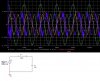
I started studing about reactive and active energies, and was referenced to LC circuit, where you can see how reactive energy is being transmitted and received by the power line.

I wanted to ask a few questions please:
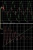
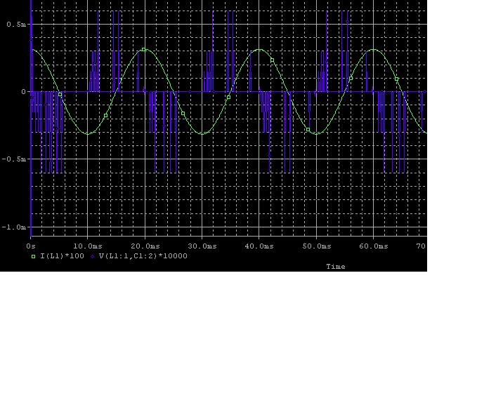
1. I dont manage to figure out why the L's voltage looks like that, VL = L dI/dt.
What is the explanation for this?

rlc2-jpg.29623


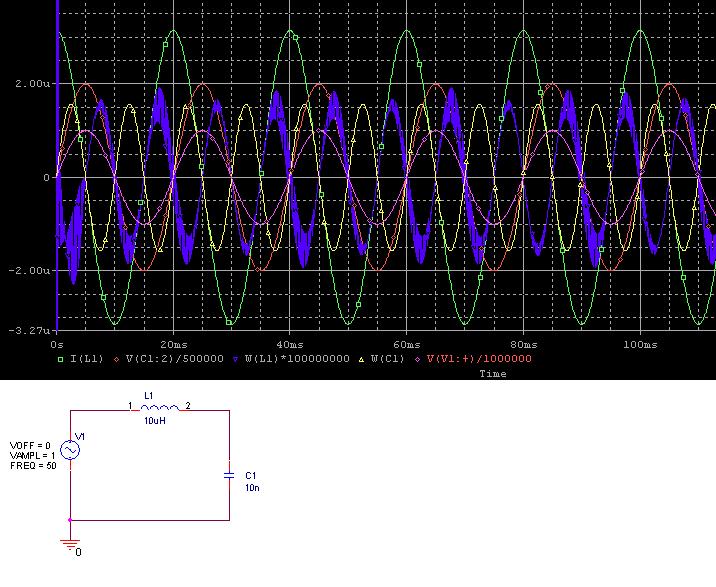
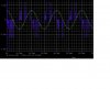
2. Why the energy of the L and C - ½LI², ½CV² - are not always possitve?

3. The energy waveform of the capacitor is much smoother than that of the inductor, which is pretty noisy.
Why is that?
Moreover, why the L's energy starts off with such large spikes that is stretched from peak to peak?

4. Is it correct to say that there are reactive energy and active energy - like in power?

Thank you very much. :)

rlc-jpg.29621
 

Attachments

  • RLC.JPG
    RLC.JPG
    90.7 KB · Views: 2,486
  • RLC2.JPG
    RLC2.JPG
    71 KB · Views: 2,132
Last edited:
Well Hello again,

It looks like because of the values you chose you are testing the limits of
your circuit analysis program more than the circuit itself.

I think you should try inductor and capacitor values that are more comparable
with the operating frequency you are driving them with. You should either
raise the operating frequency or increase the value of the inductor and
capacitor so that you see a current that is at least 1ma or even higher.
I think that will help quite a bit.
You might also try a little series resistance to dampen the LC oscillation frequency.


And yes, the energy should show up as a positive value and if you can not
get this to happen when try using:
ES=L*i(L)*i(L)/2
instead of W.
Because L is positive and 2 is positive and i(L)^2 is positive ES is always positive.
 
Last edited:
Thank you very much Mr. Al.
I indeed increased the capacitor's value to 100uF and it works fine.
I solved the ODE of this circuit and received:
iL(t) = 1/γ*[cos(ωt) - cos(θt)].
θ=1/√(LC).
ω=2Π*50.
γ=1/[1/(LC) -ω²].


for L=10uH, and C=100uH, I received:
lc-jpg.29653


1. For these L and C values, θ and ω dont have a common factor, therefore I didnt expected the waveform of iL(t) to be periodic. How do you explain it please?

2. The lower part of the above simulation shows the initial offset that the current received, since it starts off higher than it would normally be in steady state.
Here, the offset is different, its shape isn't constant (like in the R=0,L circuit), but has a cosinus waveform, and it seems like the current still managed to move into its steady state despite the lack of resistor.
Why is that?

3. I only changed the voltage source to cosine, and I received that the capacitor's voltage isn't continuous, since its starts off with 1V.
Could you tell me please how come its discontinuous at t=0?

lc_cosine-jpg.29654


Thank you very much Mr. Al.
 

Attachments

  • LC.JPG
    LC.JPG
    63.5 KB · Views: 2,255
  • LC_cosine.JPG
    LC_cosine.JPG
    30.6 KB · Views: 2,029
Last edited:
Hi again,


I think most of the problems you are encountering are due to the difference
between the pure theoretical circuit and the circuit analysis program.
Most circuit analysis programs use numerical analysis and dont actually solve
the ODE perfectly like you have here.
This means that when we compare the perfect analysis to the program analysis we
are going to see differences and so something is going to look wrong.

Note for example, that there are two frequencies: w and TH as you found,
yet we see (apparently) only one sinusoidal wave in the solution for iL(t)
with the circuit analysis program. The two amplitudes are significant too
in the pure analysis, yet we see only one component. How can this be?

There could be a couple reasons for this, but the simplest would be that the
analysis program is inserting some default nonzero value for the resistance in the
inductor. In any case, what we might do is solve the circuit using theory
but first insert some small resistance in series with the inductor before we start.
In other words, look at a circuit with R as well as the L and C, and the R would
be in series with the L and C. This could be called the bulk resistance of the
circuit and may represent both the L and C ESR. Note also that the current wave
starts out as a relatively fast oscillation, which dies out after a short time. This
is also indicative of some small series resistance, because without that resistance
this oscillation would never go away.
It goes almost without saying that if we look at the analysis program output and
try to reckon that with some assumed property about a circuit with "no resistor'
that we are going to have a problem because the analysis program actually did
insert some nonzero resistance. We thus end up theorizing about a circuit that
the analysis program knows nothing about :)

Thus, if you want to see a wave that looks like the circuit analysis program you
are going to have to insert some small series R and do the analysis again.
Alternately, you'll have to figure out how to stop your program from inserting
default values like that.

Also, a wave that has two different frequency components can still be periodic,
although the period may be longer than any single frequency component period.

You should also think about the relative sizes of the components. For example,
if you use a very very small inductor value (like 1nH) you may not see a wave
that looks like an inductor in series with a capacitor, but one that looks more
like a single capacitor. This would be because some of the effects of the inductor
may die out during the first 1ns (for example) when we are looking at tens of ms.
Thus, the size of the inductor may have to be increased in order to see a more
typical response.

BTW, if you do the calculations with the pure analysis you did you should find that
at say t=10ms you get one amplitude in iL(t) and at t=11ms you get a big change
in amplitude while the circuit analysis program shows a very small change. This
indicates that the circuit analysis program is not showing the same analysis.
 
Last edited:
Thank you a lot Mr. Al.

It does work out now.
I'll indeed analyze the RLC circuit.

In order to utilize the LC to the fullest, I see that this offset that the current received wasnt a DC offset like in the R=0,L circuit, but an AC offset, since this offset has the waveform of
cos(t/√[LC]).
What causes the offset here to be AC offset? (and not DC offset for R=0?)

By the way, what do you think about having Vc(t=0) equals 1 in the LC circuit, with cos(ωt) entry?
I also simulated a cos(ωt) entry, in RLC circuit, and received the same discontinuousity, which is very weirdI think, I'd expect VL to be discontinuous, not VC.
lc-jpg.29681
 

Attachments

  • LC.JPG
    LC.JPG
    69.2 KB · Views: 2,087
Last edited:
Hello again,


Well, im not sure if you want to call cos(t/sqrt(LC)) an offset or not, it is just the
natural oscillation frequency of L and C. You do know that a pure L and C is an
oscillator dont you? That's what that part is all about.

When you use cos(wt) (with w=2*pi*50) as the driving source you have to think about the
first microsecond, where the wave is at maximum, and that the inductor is very small
being only 10uH. As time progresses, the driving source stays relatively high as
the inductor charges and the capacitor charges, so if you look at the wave too long
after the start at t=0 it may look like the capacitor 'starts out' at the full
peak input voltage, when really it does not. It ramps up a bit as time progresses,
and follows it's oscillation characteristic as well as keeping the character of the
driving source as well. So in short, the cap doesnt really start out at full peak
voltage. We have to look at much smaller time periods, like 1 millisecond or less
to see this. We can not look at a 100ms period and hope to see this with such a
small inductor. Raising the value of the inductor to 100uH would help to see this
too.

As far as the cap voltage starting out at 1v with the RLC circuit, there must be
something else wrong with the circuit analysis program because this is not possible.
Solving the circuit for a step at t=0 results in very small cap voltage after
5us, about 50uv, and that approximates the cos(wt) wave around t=0.
It could be (maybe) that the circuit analysis program is solving for the operating
point before it begins the analysis in time...you may find a setting for that somewhere
in the user interface.
What circuit analysis program are you using btw?

Here is an exact solution for the cap voltage Vc at time t with a
step input at t=0 with large R:

BB=(t*sqrt(C*(C*R^2-4*L)))/(2*C*L)
Vc=(e^(-(t*R)/(2*L))*(-(C^2*L*R*sinh(BB))/sqrt(C*(C*R^2-4*L))-C*L*cosh(BB)))/(C*L)+1

There should be a simplification to the form Vc=1+A*e^(t*K1)-B*e^(t*K2) if you feel like finding it,
but this is just to verify that Vc(0)=0 that's all.
 
Last edited:
Hi again,

Oh well you are welcome :)

BTW when i said the program might be at fault, that is only if a test at
small times close to t=0 still result in Vc(0) being equal to 1v or near that.
An exact solution shows Vc(0)=0 as i was saying before, however we probably
have to look at the first 1us to see it correctly. The program may show
this correctly once we set it up to look closer to t=0.


I checked it out.
Normally I set the step's size to be 0.1msec.
Here, I set the step's size to 1usec, and the capacitor's voltage still started off at 1V.
Maybe i'm doing something else that's wrong, I'll officially learn Pspice only in a few months from now when I start my third year in EE.

Cheers :)
 
Hi again,

Ok that sounds good. The next thing you may want to try is to lower the
observation period time length. That is, with a small step size like 1e-7 set
the observation period time length to maybe 100us or something else small.
This will show the true start at t=0, unless of course the analysis program
can not handle this anyway.

I was able to solve the circuit for both a step response and a cosine response
and both show that Vc(0)=0. Another way to look at this however is that
for a capacitor:
dv=i*dt/C
which shows that if the cap voltage is zero to begin (t=0) then we can not have
a change of 1v for a change in time of 1us unless we have a current i that is
equal to 1,000,000 amperes! This is not possible in reality, but not even possible
in theory with this circuit because there is an inductor in series with that C that
limits the change in current with a 1v source voltage to:
di=v*dt/L
which for 10uH and a time change of 1us with a voltage of 1v we get:
di=0.1 amperes, which is far far too small to cause a change in voltage
across the capacitor of 1v. With 0.1 amperes and 1us and C=100uf we would
see a voltage increase of only 0.001v. Therefore, a rough estimate of the
voltage across the cap at t=1us is 0.001v, nowhere near 1v.

In fact initially, when the voltage jumps up to 1v on the input, there is
zero current flowing because all the voltage appears across the inductor.
The inductor then begins to allow current to flow, but this takes time.
After the current flow begins then and only then is the cap allowed to start
charging from 0v up to whatever it reaches as max.

See what happens when you set the observation time to a smaller period like
100us, and also make sure the analysis program is not setting the initial conditions
of the capacitor to v=1v, which would also cause a problem.

Also, take a look at the voltage across the inductor to see what voltage that
starts out at close to t=0.

Just to note, the cap voltage after 1us with a step response is:
0.00048370176404v
and with a cosine input voltage it is:
0.00048370176001v
using exact solutions. In other words, pretty close for very small times close to t=0.
 
Last edited:
And now for my idiotic response....

Wow! MrAL! Man, he couldn't have asked for a better resource brain than yours.

What do yo do, if you don't mind my asking. You know, work wise or hobby. I am just very impressed with your knowledge.
 
Hi,


Well, lets just say that i have studied electrical engineering quite extensively.
Now i am semi retired but still continue in electrical activity on a hobby level
and in teaching others and helping others with their various projects and
designing systems for them.

If you dont mind me asking, how did you first get involved with electronics?
 
Status
Not open for further replies.

Latest threads

New Articles From Microcontroller Tips

Back
Top