Continue to Site

Welcome to our site!

Electro Tech is an online community (with over 170,000 members) who enjoy talking about and building electronic circuits, projects and gadgets. To participate you need to register. Registration is free. Click here to register now.

  • Welcome to our site! Electro Tech is an online community (with over 170,000 members) who enjoy talking about and building electronic circuits, projects and gadgets. To participate you need to register. Registration is free. Click here to register now.

Last question for NiMH battery charger

Status
Not open for further replies.

eyevancsu

New Member
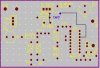
i have it all done except for im waiting for the volt reg and power transistor, and the placement of one cap. Thing with the cap is that i dont know where it would go on the pbc placement, it seems to not appear there, could anyone tell me where it would go, its 1mf cap, supposedly its number C1 which icant find?, here...
**broken link removed**
would it go right ontop of the R2 resistor just the the right of it, (near the top before the transistor)? Or where else?

schematic: **broken link removed**
under part of board: **broken link removed**
partlist: **broken link removed**

or main site: **broken link removed**

thanks

regards

ivan
 
Looks to me as if its been missed......according to the cct, it should be connected between pins 12 and 15 of the MAX.....just stick it on the underside...not elegant I know....
 
thx chippie, would anyone know what is connected aboce the R2 and below the Q1, those two dots, because i have to connect pin 11 to the right dot. also, if i used a electro 1uf cap on which pin should the negative go? or should i not use an electro?
pin 15 is the second from the top on the right? (lol sad)
plmk

thx alot
 
Connect the 1mike cap with its +ve to pin 15 on the MAX which is on the top right........... 8)


Dunno if you sussed it yet, but the component layout and the underside layout are the same i.e as seen from the component side of the board......may help in laying out :lol:
 
actually i found a mistake in my pbc, i forgot to connect pin 14 (DRV) which appears to be connected to the transistor. To waht pin of the transistor or where else would i connect it to?

on the attached pic of the component part, there are two "dots" which one is connected to the transistor and the other is connected this pin 14. should there be something put into those two pins (ie a cap, resistor, etc) that would somehow connect those two dots, if not pin 14 would just be left hanging, so to speak. kinda confusing me.

thnx
 

Attachments

  • question_for_cap.jpg
    question_for_cap.jpg
    16.2 KB · Views: 472
Pin 14 goes the base of Q1.......the common junction of Q1,R2 and C4
 
actually, this will probably be my last question, simple question i think... I made this charger to charge 4 AA 1800maH NIMH batteries totaling 7200maH, would it be possible to interchange the battery holder(holding the 4batts AA) for say a holder for 10 AAA 700maH totaling 7000maH batteries?

regards,

ivan c.
 
Status
Not open for further replies.

Latest threads

New Articles From Microcontroller Tips

Back
Top