Hi Torben,
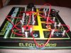
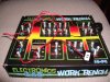
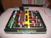
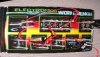
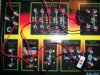
You've obviously seen these spring things before then.
So i assume its a recognised way of throwing together a bunch of components ?
Just that i dont recall anything like that.
This poster does not seem to have an 'in depth' knowledge of electronics,
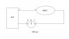
so i thought, lets go one step at a time, and get a transistor to work the siren.
Then we can move on to getting it controlled by the sensor.
If it can be done with one transistor, that makes it a little easier.
The siren is around 10 mA, so maybe one will do.
If it needs two then thats more springs i suppose.
So,
Go for simple first, yes ?
John")
(and we'll take care of the polarity too)
You've obviously seen these spring things before then.
So i assume its a recognised way of throwing together a bunch of components ?
Just that i dont recall anything like that.
This poster does not seem to have an 'in depth' knowledge of electronics,
so i thought, lets go one step at a time, and get a transistor to work the siren.
Then we can move on to getting it controlled by the sensor.
If it can be done with one transistor, that makes it a little easier.
The siren is around 10 mA, so maybe one will do.
If it needs two then thats more springs i suppose.
So,
Go for simple first, yes ?
John
(and we'll take care of the polarity too)