Continue to Site

Welcome to our site!

Electro Tech is an online community (with over 170,000 members) who enjoy talking about and building electronic circuits, projects and gadgets. To participate you need to register. Registration is free. Click here to register now.

  • Welcome to our site! Electro Tech is an online community (with over 170,000 members) who enjoy talking about and building electronic circuits, projects and gadgets. To participate you need to register. Registration is free. Click here to register now.

Laser Burglar Alarm -- Need Help

Status
Not open for further replies.
do you have some transistors to choose one ?
please describe, thank you.
 
do you have a camera or webcam,
so we can see your layout, ?

John :)
 
You have to 'Refresh' or come back to the page to see the replies.
(you may know that)

John :)
 
Anonymous321 said:
crutschow -- I sort of understand what you are explaining but not really. So how am I supposed to turn the transistor on (ie. don't make the siren ring)? Supply 0.7V to it?

Torben -- May you please tell me what you mean by the 'LDR' and the 'Vcc'? And by 'pot', I guess you mean potentiometer.

Sorry, anon. 'LDR' means light-dependent resistor; it's just a resistor which changes value depending on the amount of light falling on it. Also referred to as 'CdS cells'.

'Vcc' is just another way of saying 'V+' or 'the positive supply voltage'.

You got the 'pot' in one. :)

But guys, I'm trying to read as much and fast as I can about these darlington transistors but I have a question: do they come premade in pairs? Or can one simply connect 2 transistors in series or something and that will work? Also, I won't be able to buy anything else most likely anymore b/c the The Source (Radio Shack in America) in my town doesn't sell electronic components anymore and I had to drive 1 hour away from here to another Source just to get the components that I have.

You can get Darlingtons either as a single component (looks just like an ordinary transistor) or you can make your own with two transistors. Google 'Darlington wikipedia' for more information.

At school, my friend made a suggestion that I make a very basic circuit utilizing just the buzzer, the photocell, and a battery. I'll post the schematic.

Mmm....I am away from my gear right now so I can't test that, but I have a feeling it won't work as well as you might hope.

I appreciate your guys' help. But like some of the things (like 555, inverters, etc.) that you guys are talking about I don't know about nor do I have access to (w/ the limited time I have and the resource being and hour drive away) and I really just want a simple design. I know the headache that I'm giving you guys and I apologize deeply. I thank you all once again for sticking with me (I hope).

Ah, gotcha. OK, skip the output timer. The inverter is just one transistor and a resistor configured so that the output is the inverse of the input, and a 555 is just an 8-pin timer chip which is ridiculously useful. ;) If you just need to prove the concept of causing your buzzer to buzz, no matter how briefly, when the beam is broken, you can safely ignore the inverter/555 thing I mentioned.

What town are you in? There may be something besides The Source (even worse than Radio Shack if that is possible). Heck, in a pinch you might be able to give a local TV repairman $10 for a few bits and pieces; you never know.

Is the purpose of the exercise to show that you can design the actual circuit, or just to show that such circuits *can* be built from plans? If the latter I could just post a link or a schematic for you.


Good luck,

Torben
 
Are you assembling this on one of those 'breadboard' kit things,
with rows of holes that you poke the bits into ?

John :)
 
Yes, I have a multimeter. It's a Mastercraft Pocket Analog Multimeter.
Specifications:
DCV...............10 V/250 V/500 V (2 K:eek:hm:/V)
ACV...............10 V/250 V/500 V (2 K:eek:hm:/V)
DCA...............500:mu:A/10mA/250mA
:eek:hm:.............2K:eek:hm:/200K:eek:hm: (centre 3.6 K:eek:hm:)

Yes, I also have resistors. 3 packs.
1st pack:
1/4-watt, 5% Carbon resistors, 2-pcs of each
10, 22, 33, 47, 220, 330, 470, 1k, 2.2k, 3.3k, 4.7k, 10k, 22k, 33k, 47k, 100k, 220k, 330k, 470k, 1m ohm

2nd pack:
1/4-watt, 5% Carbon resistors, 5-pcs of each
100, 220, 330, 470 ohm

3rd pack:
1/8-watt, 5% Carbon resistors, 5-pcs of each
10, 22, 33, 47, 220, 330, 470, 1k, 2.2k, 3.3k, 4.7k, 10k, 22k, 33k, 47k, 100k, 220k, 330k, 470k, 1m ohm

So obviously lots of the same ones. I bought pack 1 and pack 3 b/c they were different watts. I didn't (and don't) know which one would be best.

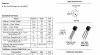
Yes, I have transistors to choose. 2 packs.

1st pack:
On the front of the pack, it says NPN-Type Switching Transistors.
On the back:

Silicon..........NPN
Typical hFE...200

Maximum ratings
VCE.............30V
IC................800mA
Dissipation.....1.8W
Then it tells me that these are designed for high-speed, medium power switching and general purpose amplifier applications. And then it tells me which leads are the B, C, and E.

2nd pack:
On the front of the pack, it says PNP Transistors and that they're "Similar to type 2N3906".
On the back:

This 2761604 is designed as a general purpose amplifier and switch. The useful dynamic range extends to 100mA as a switch and to 100 MHz as an amplifier.
Collector-Base Voltage........60V
Collector-Emitter Voltage.....40V
Emitter-Base Voltage..........6V
Dissipation........................350MW
Then it describes which pin is the B, C, E.

And, unfortunately I do not have a camera or a webcam. My cousin has them and I suppose he may be able to lend one of them to me...What about skype?

And sorry for the late reply.
 
Last edited:
thats Ok.

I'm thinking now.
 
are you using one of those 'breadboard' kit things,
with rows of holes that you poke the bits into ?
 
Can you tell which pins are which on the transistor(s)
This is necessary.
 
john1 said:
are you using one of those 'breadboard' kit things,
with rows of holes that you poke the bits into ?
No, none of the Sources had them. They had PC and IC boards but I believe I'd need to solder and I don't even have soldering material let alone know how to solder anyway.

But I am using steel springs to connect my wires. It's just this cardboard box with small holes that many small steel springs are inserted in. And I just put my wires on those springs.
 
Torben -- "Is the purpose of the exercise to show that you can design the actual circuit, or just to show that such circuits *can* be built from plans?"
Not even any of those. It's just to do a research project and build any model. It's not even related to circuits. It's an open project and I wanted to do mine on alarm detection methods. Like, some girl in my class today presented and she did her project on quarks. Her model was just like a sock with two styrofoam balls in it. Of course, she did get pretty much destroyed by the teacher though..

John -- Which pins are on the transistors? Well um, Pin 1-Emitter, Pin 2-Base, Pin 3-Collector. Is that what you mean?
 
Okaay ...

got to feed my cat, she's actually rattling her dish.
Back v soon
 
Torben--Well it's a small town near Lake Huron in Ontario. And it really doesn't have much. Anything useful has probably already closed by 6pm (atleast The Source and our local internet provider store, which I believe closes at 5).
 
If it's really needed, I can try to get a camera. One of my friends may be able to lend me one. But also, what about msn messenger or skype?
 
are they like this ?
 

Attachments

  • 2N3906.JPG
    2N3906.JPG
    66.5 KB · Views: 183
If you can borrow a camera,
it would help,
but i think we'll struggle through.

John :)
 
Status
Not open for further replies.

Latest threads

Back
Top