Electro Tech is an online community (with over 170,000 members) who enjoy talking about and building electronic circuits, projects and gadgets. To participate you need to register. Registration is free. Click here to register now.
Welcome to our site! Electro Tech is an online community (with over 170,000 members) who enjoy talking about and building electronic circuits, projects and gadgets. To participate you need to register. Registration is free. Click here to register now.
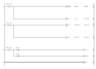
I have a modbus protocol example on gxworks2 software. But the problem is i cannot understand what are those ladders means. So please help a bit to understand what is this means step by step.
Thank you.
With that specific PLC, X's are external inputs bits to the PLC; Y's are output bits from the PLC to whatever it controls.
Some others, eg. Siemens, use I (or E) for Input/Eingang and Q (or O) for Output/ Outgang.
(Depending on the system age - earlier ones used German mnemonics).
M is a "mark", internal memory flags for temporary storage of states or values.
Some M bits are used to interface with the PLC system and special functions in some PLCs; others use different letters.
Some PLCs use F for flags.
The MOV instruction is a move, transferring a numeric value from one location to another, if the enable input from the ladder to the left is true.
The ZRST is apparently "Zone reset - clear all the marks in the range following.
As Max says, you need the correct programming manual for that PLC to know exactly what different parts of the program are doing;
To save some time looking at the external references, here is my ladder logic cheat sheet.
Ladder diagrams originated in pre-computer days as a systematic way of drawing relay logic schematics.
The vertical lines on the left and right sides of the diagram represent the power supply rails: line voltage (hot) on the left side, and neutral on the right side.
The things that look like capacitor schematic symbols are normally open contacts: either PLC inputs from sensors, or contacts off of internal relays.
The things that look like capacitor schematic symbols with a slash through them are normally closed contacts: either the negation of an input sensor signal, or the negation of an internal relay state.
The thing on the right hand side immediately before the vertical neutral rail is the output for the ladder rung. It may be a physical output of the PLC, or it may be an internal relay coil.
A major difference between logic done with relays (which the PLC's emulate) and solid state logic gates (AND, OR, NOT, etc.) is that:
a) Whereas logic gates typically have multiple inputs, a relay has only one input: the relay coil. This means that you have to combine inputs, as relay contacts, in series and parallel to get the required logic function, and then feed it to the relay coil. In essence the logic function is not done in the relay itself, but in the series/parallel wiring of the contacts that control the relay.
b) Whereas a logic gate has only a single output, a relay coil has multiple outputs, both normal (N.O.) and inverted (N.C.). These multiple outputs are the basis of the series/parallel logic that control subsequent relays.
Relay ladder logic can do everything that that gate logic can do, but it requires a different way of looking at the problem. Once you're familiar with relay/ladder logic, it's very easy to follow. This is the reason why PLC vendors went with ladder logic in the first place. Electricians were very familiar with relay ladder diagrams that had been use for many decades before PLC's became available.
To save some time looking at the external references, here is my ladder logic cheat sheet.
Ladder diagrams originated in pre-computer days as a systematic way of drawing relay logic schematics.
The vertical lines on the left and right sides of the diagram represent the power supply rails: line voltage (hot) on the left side, and neutral on the right side.
This is the reason why PLC vendors went with ladder logic in the first place. Electricians were very familiar with relay ladder diagrams that had been use for many decades before PLC's became available.
And the typical paper copy ladder method in Europe is to use top down method of illustrating a ladder program, instead of left to right, the symbols are quite different also.
Historically the PLC was invented in 1968 at the behest of G.M. who wanted to improve the method of trouble shooting by on floor maintenance electricians.
A guy named Dick Morley managed to come up with the PLC idea using Boolean logic symbols, just working over a week-end!
This site uses cookies to help personalise content, tailor your experience and to keep you logged in if you register.
By continuing to use this site, you are consenting to our use of cookies.