Continue to Site

Welcome to our site!

Electro Tech is an online community (with over 170,000 members) who enjoy talking about and building electronic circuits, projects and gadgets. To participate you need to register. Registration is free. Click here to register now.

  • Welcome to our site! Electro Tech is an online community (with over 170,000 members) who enjoy talking about and building electronic circuits, projects and gadgets. To participate you need to register. Registration is free. Click here to register now.

Lab bench testing power supply breadboard?

Status
Not open for further replies.

JamesC13

New Member
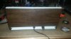
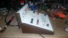
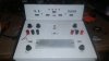
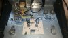
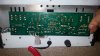
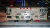
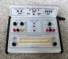
Hi so this is my first post to this site I do apologize if it has the wrong area I was given a basically what I think is a variable power supply, the terms for me getting this nice thing for free was the fact that it is old one and had been through a fire so it was not damaged however had smoke damage so the person who owned it rebuilt it and painted it and because he had had it for so many years he knew it by heart now I have no way of telling what is what and it looks very nice and very tempting for me as I just started out playing around with circuits. So I was hoping that some veteran here might be able to identify it and send me a picture so that I can relabel and Mark out everything so that I can start using it. It is made out of wood siding and steel. thank you very much for any help thanks guys:
 

Attachments

  • IMG_20160814_180936.jpg
    IMG_20160814_180936.jpg
    1.2 MB · Views: 367
  • IMG_20160814_180923.jpg
    IMG_20160814_180923.jpg
    1,022 KB · Views: 379
  • IMG_20160814_180902.jpg
    IMG_20160814_180902.jpg
    1 MB · Views: 368
  • IMG_20160814_183223.jpg
    IMG_20160814_183223.jpg
    1.5 MB · Views: 385
Hi and welcome.
looking at the case, and this is just a guess I'd say its heathkit.
Looks like a dual power supply, one with current limit, a few leds and a couple of pots for use with the breadboard, usefull gizmo for a beginner and a seasoned enthusiast.
 
It was made using a part with a 1973 date code and you can start learning how to use it with a DMM to measure the socket pins.

the isolated pots have 3 pins and if you number them 123 the CW position of the wiper is usually pin 3 and the CCW position is pin 1 which you can check. THe value seems to be 1K

You can measure the voltage range of the pots for the LM317 type regulator

Power switch is on centre.

It looks like a DIY project, but you are going to have to measure the outputs for +(red) -(black) and earth ground.
 
Last edited:
Yeah I did guess that might be homemade so here is the top circuit board. Thank you both very much for the input I really appreciate all the help as a noob
 

Attachments

  • IMG_20160815_013315.jpg
    IMG_20160815_013315.jpg
    1.5 MB · Views: 367
  • IMG_20160815_013305.jpg
    IMG_20160815_013305.jpg
    1.5 MB · Views: 353
The rear board, looking at the layout and making educated guesses, connector u1 is a logic squarewave output with the 2 associated switches controlling frequency/duty, u2 maybe a sine/triangle wave generator, u3 looks as though it goes to the 4 leds as status indicators, and u5 maybe goes to the 4 associated switches, they probably pull the connector pins to ground.
We could probably tell more with front & back pics of the other board too.
 
Okay so after hours of looking around figuring out it was made in the seventies I managed to find a single word which led me to this single thumbnail picture that I was able to find so it is a mass produced product it is just very old and I guess rare
 

Attachments

  • 391466180235_1.jpg
    391466180235_1.jpg
    15.6 KB · Views: 344
Not answering any of your questions, I know, but redrawing the schematic would be simple (everything seems clear enough) and not so many components.

Even if it sounds unnecessary, check continuity between all banana female connectors.

Identifying what each IC does, could help a lot. The 7403 is a really dated one (NAN gates?).

Have you got a scope?
 
Having seen more I'll make some other educated assumptions.

I think I was close with the back panel, allthough looking at the pic of the complete one the switches at the left on the back panel are not freq and duty, they look like they are just logic hi/lo from the output sockets, those switches probably just go through a logic gate to the output socket.

The 2 knobs on the left look they they are a + and - power supply using the lm317 and lm337, so maybe black is gnd, red is - volts and yellow + volts, the 2 pots adjusting each one seperately.
The slide switch inline with the sockets is obviously main power.
The knob on the right looks like it might be a signal generator, and the switch maybe selects one of 2 waveforms, which is then outputted on the sockets.
The 2 pots at the bottom are just wired to their sockets for general use.

Try putting a meter on the left bannana sockets, ground to the black socket, and then probe the red and yellow sockets while twiddling the adjacent knobs, see what happens.

Looking at the date code its early 80's, or someone repaired it with early 80's parts.
 
Last edited:
This looks suspiciously similar just a plastic box, I wonder if the original owner put it in the wood box after the fire damage, and like I said heathkit, I bet the boards are the same:


This is also similar:


Found a very similar one on ebay:

**broken link removed**

Finally if you follow this link and scroll down to ET-3100 you'll see the pdf manual for the above which looks as though it has the same stuff as yours.
https://www.vintage-radio.info/heathkit

I have spent too much time looking for junk on the net and as such I can be good sometimes at finding info.
 
Last edited:
That looks like it.

MC1455 timer , NAND gate IC's and some LED drivers indicators for "logic probes"
 
Status
Not open for further replies.

Latest threads

New Articles From Microcontroller Tips

Back
Top