Continue to Site

Welcome to our site!

Electro Tech is an online community (with over 170,000 members) who enjoy talking about and building electronic circuits, projects and gadgets. To participate you need to register. Registration is free. Click here to register now.

  • Welcome to our site! Electro Tech is an online community (with over 170,000 members) who enjoy talking about and building electronic circuits, projects and gadgets. To participate you need to register. Registration is free. Click here to register now.

LA3220 Schematic electret pre-amp need help

Status
Not open for further replies.

josedad

New Member
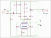
I am new to this forum, and a novice too in electronic. I want to make a pre-amp mic base on LA3220. I found a thread here weeks ago and start to make my own. But it doesnt work. I still learning reading Schematic perhaps I did not correctt. I build based on Schematic posted by audioguru 12 years ago.
https://www.electro-tech-online.com/threads/la3220-application.15329/
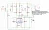
Design by audioguru
la3220_mod-gif.4624


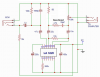
I try to read and inteprete
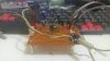
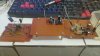
Here`s what I got
my-intepretation-jpg.109230

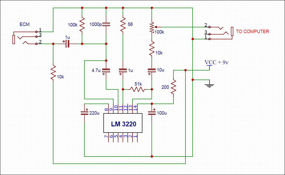
( Sorry I misstype the IC as LM3220)

Perhaps I did it falsely

Help me Audioguru.
 
Last edited:
I suspect the problem is that you have the output ALC (Automatic level control.) (Pin 9) control connected to the input signal from the microphone but you have nothing connected to the input of the ALC control. (Pin 7) If you do not want to use the ALC function then leave pin 9 disconnected. If you do want to use the ALC then you you need the components that rectify the preamp output. (300K resistor, 47 uF capacitor, 2 diodes, 4.7 uf capacitor, 680 ohm resistor) The right hand end of the 608 ohm resistor should be connected to the negative side of the 10 uF capacitor that is connected to pin 13.

Les.
 
The LA3220 seems to be obsolete. It's not listed by the main component distributors. LM3220 is not a listed IC either.
 
Hi josedad,
The first thing I noticed was that the old Sanyo IC (Sanyo was bought by Panasonic) was not powered because you did not connect pin 1 to the 0V of the power supply (battery?).
Then I noticed that you have 200 ohms in series with the + of the power supply and the + of the IC that will not reduce power supply noise because you have the mic directly powered from the (noisy?) power supply. Remove the 200 ohm resistor.
Then I noticed the ALC problem and I agree that pin 9 should be disconnected.
Then I noticed that you replaced the 22uF capacitor in the feedback with only 1uF so the low frequencies will be cutoff below 2860Hz producing no bass sounds and mess up speech sounds. Even the recommended 22uF will cutoff some deep bass sounds.
The 10k resistor is not needed in series with the volume control.

Is jose your son?? I am briandad.:)
 

Attachments

  • LA3220 mic preamp.png
    LA3220 mic preamp.png
    401.5 KB · Views: 364
Thank you for all replies.
I will try rebuilt this weekend.

I suspect the problem is that you have the output ALC (Automatic level control.) (Pin 9) control connected to the input signal from the microphone but you have nothing connected to the input of the ALC control. (Pin 7) If you do not want to use the ALC function then leave pin 9 disconnected. If you do want to use the ALC then you you need the components that rectify the preamp output. (300K resistor, 47 uF capacitor, 2 diodes, 4.7 uf capacitor, 680 ohm resistor) The right hand end of the 608 ohm resistor should be connected to the negative side of the 10 uF capacitor that is connected to pin 13.

Les.
my priority now is making it work first. Maybe later on I will try the ALC feature and see what will coming up.


The LA3220 seems to be obsolete. It's not listed by the main component distributors. LM3220 is not a listed IC either.
Yes, I`m sorry, I mistype it, since it my first time using easyeda too.


Hi josedad,
The first thing I noticed was that the old Sanyo IC (Sanyo was bought by Panasonic) was not powered because you did not connect pin 1 to the 0V of the power supply (battery?).
Then I noticed that you have 200 ohms in series with the + of the power supply and the + of the IC that will not reduce power supply noise because you have the mic directly powered from the (noisy?) power supply. Remove the 200 ohm resistor.
Then I noticed the ALC problem and I agree that pin 9 should be disconnected.
Then I noticed that you replaced the 22uF capacitor in the feedback with only 1uF so the low frequencies will be cutoff below 2860Hz producing no bass sounds and mess up speech sounds. Even the recommended 22uF will cutoff some deep bass sounds.
The 10k resistor is not needed in series with the volume control.

Is jose your son?? I am briandad.:)

Hi Briandad, yes your guess is right. Jose is my son. :)
Thank you for the correction. One month ago I build Mic preamp with 1 Transistor, but I found the noise is too high. When I search on local electronic shop they sell this preamp head kit using old Sanyo LA3220 for cheap. It said could make low noise HIFI preamp Mic with it. So I bought some and salvage the components. Then I search on the net and found your schematic.
Having bass output is my consideration too, since electret tend to respond high frequency sensitively. When you said that 22uF will cutoff some deep bass sounds, can it changed to 47uf or else?

I found the bass and treble schematic from extrmecircuits.net
ACTIVE_BASSTREBLE_CONTROLLE.gif

Can it be applied to the output of the preamp? since it powered by the same 9v (yes I use battery).

Regards
 
A half decent electret mic has a perfect frequency response to very low frequencies. But most speakers have reduced low frequency levels. The calculation of the -3dB frequency of an RC like your 1uF and the 56 ohm resistor is 1 divided by (2 x pi x 1uF x 56 ohms)= 2860Hz which is midrange frequencies and the bass will be gone. W15dB at 100Hz. With 22uF the -3dB frequency is 130Hz which is upper bass frequencies. With 47uF the -3dB frequency is 60Hz and is a bass frequency but not a deep bass frequency. Use 100uF for a -3dB frequency of 28.6Hz. Use 150uF if you have music with deep bass and a very good sub-woofer.

The datasheet for the LA3220 shows switched bass boost. It is the 33nF capacitor in series with the 4.7k resistor connecting to the 56 ohm resistor and the 22uF capacitor. They actually reduce midrange and high frequencies but leave the bass at full level. The +3dB frequency is calculated to be 1032Hz and the maximum amount of boost is about +17dB at 100Hz. A graph is shown in the datasheet.

Here is the frequency response of a half decent electret mic going perfectly down below 20Hz:
 

Attachments

  • Electret microphone.PNG
    Electret microphone.PNG
    16.8 KB · Views: 186
A half decent electret mic has a perfect frequency response to very low frequencies. But most speakers have reduced low frequency levels. The calculation of the -3dB frequency of an RC like your 1uF and the 56 ohm resistor is 1 divided by (2 x pi x 1uF x 56 ohms)= 2860Hz which is midrange frequencies and the bass will be gone. W15dB at 100Hz. With 22uF the -3dB frequency is 130Hz which is upper bass frequencies. With 47uF the -3dB frequency is 60Hz and is a bass frequency but not a deep bass frequency. Use 100uF for a -3dB frequency of 28.6Hz. Use 150uF if you have music with deep bass and a very good sub-woofer.

The datasheet for the LA3220 shows switched bass boost. It is the 33nF capacitor in series with the 4.7k resistor connecting to the 56 ohm resistor and the 22uF capacitor. They actually reduce midrange and high frequencies but leave the bass at full level. The +3dB frequency is calculated to be 1032Hz and the maximum amount of boost is about +17dB at 100Hz. A graph is shown in the datasheet.

Here is the frequency response of a half decent electret mic going perfectly down below 20Hz:
I use Panasonic WM-034 and WM-058, both response to low frequency quite good, and the high frequency as well. That the best I can get here.

I try to redraw the correction include with switched bass boost.
I assume that datasheet refer to music use, but I think its worth to try.
Please do correction if I draw wrongly.
 

Attachments

  • Sanyo preamp.jpg
    Sanyo preamp.jpg
    124.2 KB · Views: 269
The datasheet schematic clearly shows that your bass boost parts were in the wrong location.
That is a lot of boost. To have the same volume at high frequencies as before then the volume must be turned up +17dB and the output power of the amplifier at 100Hz must be about 14 times more. Also your little speaker must survive 14 times more power. Here is the correction:
 

Attachments

  • bass boost.png
    bass boost.png
    417.8 KB · Views: 295
After 2 hours soldering, It works like a charm. Thanks audioguru, Les Jones, alec_t .

Is it possible to increase the gain little bit? I will try to activate the other side to make it stereo for outdoor recording if possible.
 

Attachments

  • 20171126_194051 r.jpg
    20171126_194051 r.jpg
    1 MB · Views: 195
Why are the wires on all your parts so looong? Usually parts touch the board so that their wires can be cut short.
As I said before, the bass boost works by cutting the levels of mid and high frequencies. You can increase their gain +6dB by reducing the bass boost 6dB. Change the 4.7k resistor to 10k and change the 33nF capacitor to 15nF. You can test very high gain by disconnecting the R and C bass boost parts where they join together..
I intentionally keep all the wire uncut and solder its edge, so when I need to change and desolder or re arrange will ease me. Its a prototype actually, once it works I will build in tighter small lay-out. Since for some reason I dont like breadboard.
Perhaps I will make a switch whether I use bass boost or just by pass it for higher gain. Thanks again audioguru, send my hello from Indonesia to Brian. :)
 
Como Estas, Jose's dad. My wife is from Spain but that is all the Spanish that she and Night School taught me.
Your long wires and the many rows of contacts on a solderless breadboard have capacitance between them that cause problems like oscillation in an amplifier and amplification in an oscillator. Also the long wires are antennas that pickup all kinds of interference.
Adios, mi amigo.
 
Hi, audioguru, its me again. I have tried to build another one with a neat and smallest lay-out, but the gain is too low, even-tough the volume is in max, it only reach -30 db (from audacity, and I already boost the mic setting for 50%). I thought it might be something wrong with my build. So I build another once again, this time I make more space perhaps the tight lay out effect the component works, but when I try to record via audacity, the result is the same. I did try to disconnect the bass boost, but the result is even worst. The volume decreased significantly. What should I do?


Como Estas, Jose's dad. My wife is from Spain but that is all the Spanish that she and Night School taught me.
Your long wires and the many rows of contacts on a solderless breadboard have capacitance between them that cause problems like oscillation in an amplifier and amplification in an oscillator. Also the long wires are antennas that pickup all kinds of interference.
Adios, mi amigo.
:) even-tough my son`s name sounds Spanish but actually I`m Asian, so are my sons. I don't speak Spanish too we speak Indonesian. I know Spanish but very little, far less than you do, I bet. Once I learn french, but since I never practice it, I almost forgot every words. :p
 

Attachments

  • 20171128_210505 upload.jpg
    20171128_210505 upload.jpg
    189.1 KB · Views: 202
Hi Jose's dad,
Some people in Canada speak French so all government things and all packages have English and French and all kids are taught French.
I also learned French a long time ago but never used it so I can't remember much of it.
Oddly, kids in the French province are not taught English and stores signs in the French province must show only French words, not any English.

I am glad that you made your project neat and tidy.
 
You must have a wiring problem because without bass boost the gain above 130Hz is extremely high at 912 times.
With bass boost the gain at high audio frequencies is 77 times.
What resistance is the load?
 

Attachments

  • bass boost2.png
    bass boost2.png
    463.8 KB · Views: 248
Measure the output level from your preamp with no load then connect it to your computer. The level should not drop much because the output impedance of the recorder should be much lower than the input impedance or resistance of your computer.
 
Hello again, audioguru . Happy new year 2018.

Its me again. I have build the preamp with a little replacement for better result. For couple weeks I tried to study opamp for good. Later on I check my chip and I found some question from it. I bought the IC along with the head preamp kit soldered, When I check the schematic given on the built preamp, I found difficulty to Identify what kind circuit on that.

20180105_173413.jpg

takon.jpg


I cant identify what kind of amplifier on the circuit. Since the output doesnt conect to the inverting input, I cant say thats a negative feedback. But I might be wrong.

And I dont know what PC is (pin 3 and pin 12)

Can anybody explain them to me?

Thx
 
The datasheet has circuits with negative feedback so I do not know why your circuit is missing it.
The datasheet explains what are the functions of pin 3 and pin 12.
Why don't you read the datasheet like I did a minute ago?
 

Attachments

  • LA3220 preamp.png
    LA3220 preamp.png
    167.7 KB · Views: 263
Status
Not open for further replies.

Latest threads

New Articles From Microcontroller Tips

Back
Top