Continue to Site

Welcome to our site!

Electro Tech is an online community (with over 170,000 members) who enjoy talking about and building electronic circuits, projects and gadgets. To participate you need to register. Registration is free. Click here to register now.

  • Welcome to our site! Electro Tech is an online community (with over 170,000 members) who enjoy talking about and building electronic circuits, projects and gadgets. To participate you need to register. Registration is free. Click here to register now.

L293N Motor running slow or not at all

Status
Not open for further replies.

Lyncos

Member
Hi,

I'm new there and pretty new to the robotic world and i'm trying to do a project with a L293N to drive my motors from an Arduino board.

Let me explain the problem....


I have tried 2 motors

First one is a small 5v ( i suppose) motor comming from an old CD-ROM drive.
The Second one is a unknown 12v motor.


The problem is:

The small motor when connected to L293 is running about at half speed then when connected directly to the Power Supply. I didnt calculate the amps but it should be really low.

The bigger 12v motor is not running at all when connected to the L293. When connected directly to the power supply it run fine and i'm observing a peak of about 1.2Amps at startup then it runs at about 600mA. When Applying PWM to the input pin I can ear noise. It start to run when I connect 1 of the 2 wires of the motor to the ground it running fine and at full speed.


The Facts:

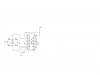
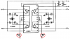
The Schematic I'm using is the one comming with the specsheet of the L293N IC for Bi-Directional. I tried with and without the diodes I used (251D) but I think the diodes are just a higher level of short circuit protection.

I also tried of stacking 2 L293N chip and using all the 8 bridges on it ... with the sames results.


the +5V for IC logic is connected to my arduino 5V supply


I tried with a 1000uF Capacitor on the 12V line too without any succes.


I also tried to connect 1 input pin to groun and the other to +5V with the same problem.


I'm kinda out of idea i'm working on this for about 7hours and browsing the web without any clue of what happening....


I'm aware I may have not included all the detail you need to help me but will be pleased to provide them for you to help me.


thanks.
 
Last edited:
The datasheet for the L293 shows that each part of it has a max voltage drop of 1.8V at 1A of current. Then your 5V supply is reduced to only 1.4V to the motor.

With a 12V supply the motor gets only 8.4V.
 
I know about the voltage drop. but the 12V motor is running at about 4 volts when i connect it directly to the Power Sup... it should run at 8.4 ? I also tried with a 16V power source with the same results.


And also I tried with 2 Different chip just in case the 1st one were a defective one .. but exact same results
 
The 12V motor might not start if the voltage to it is only 4V.
It should have run very fast if your 16V power supply had enough current.
 
But.. Why when I connect 1 motor lead to the high output of the L293 and the other to the ground It works fine ? Like this I can PWM the motor and everything is just fine... but like this I loose reverse..


When Both leads are connected to the l293 outputs its not running at all...


Let me check the voltage at output .. with the motor connected and not connected..

I come back to you soon.
 
Ok doing the tests now:


Power Supply Output voltage
15.58V

The VSS pins have 4.98V comming from the arduino 5v supply (USB)

Input pins: 2 and 9
Connected to the Arduino board
Pin 2 have 4.08V (HIGH)
Pin 9 have 0.0V (LOW)


12V motor connected to pins 3 and 8
Voltage at motor 0.25V

If i disconnect Motor :
Voltage at pins 3 and 8

15.20V


BTW I removed the diodes from the circuit because i'm not sure which ones I should use.. maybe this is the problem....

Maybe this could help better see the problem.. when I connect the motor the voltage drop to near 0 ..
 
Last edited:
By the way, I don't know what kind of motor it is ..

It's a dual Axle Johnson motor with permanent magnets and on the top of it I can read

Hong Kong 888 PAT P.

thats
 
OMG I made a big mistake.. its not a L293N its an L293E just miss typed it on topic and re used it thru the Thread....

Is there any way to change the thread title ?
 
If your L293 has 16 pins then pin 8 is the positive power supply for the bridge circuit, not an output to a motor.

Since you removed the protection diodes then the inductance of your motor made high voltage spikes that probably destroyed your L293.

Please post your schematic for us to see if anything else is wrong.
 
I have the 20 pins IC and the chip is not destroyed, I tested all the inputs 1 by 1 in a 1 channel configuration (no reverse) also tested both direction on all channels and they all works fine. The problem is when I try the 2 channel configuration to have the reverse.

Also today I tested with a 2 Amp Power sup to be sure it's not the power supply but since the voltage was not dropping at the powersupply when I connect the motor I was pretty sure it was enought power.


What software is best for Schematics ? I have it on paper but have no scanner.

I will show you all the working Schematics and the one not working too.
 
The circuit i'm trying to get workin is the one on the left ... the ones on the right side are all working on any pins.

https://www.electro-tech-online.com/attachments/esp02-sep-16-gif.22388/


I have double checked the pins for the 20 pins chip and all the connection are right from the beginning the Enable pin is on +5 and one of the inputs is HIGH and the other one is LOW

I have checked lots of circuit on the net ... and they all using the same configuration and seen no problems.. but since I have checked all the outputs independently in both current direction i can conclude that the IC is working.. I also tried another IC and I have same kind of results...
 
You attached the schematic for the 16 pins L293B or L293D.
Copy and post the schematic you are using from the datasheet.
 
Ok I have made the Schematic and attached it to this post. With this it should be clear how i'm using it

I have removed the MCU inputs from the equation just to be sure he is not in cause.. I'm using +5V from an USB port thru the MCU.


I hope is much clearer now


Sorry about the confusion
 

Attachments

  • LD293E.jpg
    LD293E.jpg
    78.3 KB · Views: 722
Last edited:
The datasheet has the sensing pins 4 and 7 connected to ground through resistors with their value not specified and also shows pins 4 and 7 connected together and connected to a 1 ohm resistor to ground. You forgot to connect them.

The datasheet does not explain the function of pins 4 and 7. Maybe they limit the max current.
 
They are for sensing the current the motor is using.. i read somewhere they can be leaved Open... but not sure... im not sure what resistance value I should use...
 
The datasheet shows you 1 ohm which limits the current to 2A.
Without a resistor the current is nothing.
 

Attachments

  • L293E.PNG
    L293E.PNG
    22.1 KB · Views: 1,351
Thanks a lot it is working just fine .. I tried with a piece of wire since I have no 1ohm at the moment .. and the motor start running... I will buy 1ohm resistor tomorrow continue experiments but it should be good now.

Can you please give me the link of the Datasheet where you found the information please ?


Thanks a lot for your devoted help
 
Are you good with Voltage divider and MCU ? i would like to check the voltage drop at the 1 ohm resistor to know the Current my motor is drawing.
 
You should never make a circuit without the datasheet. I get my datasheets from www.datasheetarchive.com where I can select the manufacturer. Only ST Micro makes the L293E but other manufacturers make other L293 ICs.
 
Status
Not open for further replies.

Latest threads

New Articles From Microcontroller Tips

Back
Top