Continue to Site

Welcome to our site!

Electro Tech is an online community (with over 170,000 members) who enjoy talking about and building electronic circuits, projects and gadgets. To participate you need to register. Registration is free. Click here to register now.

  • Welcome to our site! Electro Tech is an online community (with over 170,000 members) who enjoy talking about and building electronic circuits, projects and gadgets. To participate you need to register. Registration is free. Click here to register now.

Kooky?: Replacing battery power with leads...

Status
Not open for further replies.

chconnor

Member
Well, my latest half-baked idea, curious to know if I'm off-track. Should be an easy answer. :)

I have a number of devices that take batteries, and I'd like to avoid purchasing batteries (even rechargeables).

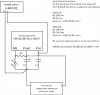
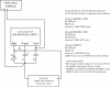
What I'd like to do is wire leads into the contacts of the device(s) going through a simple circuit from an AC/DC converter wall wart.

I'm figuring that an e.g. 2-AA battery compartment wants 3V at whatever current (I'm assuming my AC/DC converter will have ample current compared to batteries?).

I'm figuring that the converter, say it's putting out 9V, needs a voltage-dropping resistor (which wastes power/makes heat?) or a DC voltage converter (which, if cheap, makes messy/noisy power and also isn't too efficient?) to get to 3V.

I'm figuring that I can use a pair of dead batteries with the leads attached to the ends (one +, one -) and the other ends of the batteries covered with non-conductive material (to prevent short circuit), so I have an easy way of getting the leads down into the battery compartment to their destinations.

Curious to know if those assumptions have anything to do with reality, and the best way to achieve the desired voltage?

There's probably a product for this out there? I like to DIY, especially because I have a pile of various DC adapters.

Thanks a lot!
-C
 
I'm figuring that an e.g. 2-AA battery compartment wants 3V at whatever current
Something like that.
(I'm assuming my AC/DC converter will have ample current compared to batteries?).
This depends on the powered device and of course the converter. As a starting point, check the label on the converter.

I'm figuring that the converter, say it's putting out 9V, needs a voltage-dropping resistor (which wastes power/makes heat?) or a DC voltage converter (which, if cheap, makes messy/noisy power and also isn't too efficient?) to get to 3V.
Depending on the device you're powering, either option may be effective. If the device has a low current consumption, then a linear regulator is fine. If current is higher, then you may want to put the regulator on a heatsink or use a switch-mode supply (which is more efficient unless set up incorrectly).

Switch mode supplies will have some ripple, but if this is a problem, follow it either with a filter or a linear regulator.
 
Dead batteries eventually leak and do bad things. Mostly make a mess, which is difficult to clean out. Use some plastic dowel and a couple of screws. Works pretty well, screws hold the wires, and make good terminals. You can add a washer or two if you cut the dowel too short for a nice fit...

Solder the leads directly, or add a socket if you have room...
 
Ok.

Thanks folks. Good to know I'm on the right track, or at least that it's possible.

Something like that.
This depends on the powered device and of course the converter. As a starting point, check the label on the converter.

Sure sure... As a ballpark, I'm talking about converting something like a 1 or 2A 9V converter to 3V to run a digital camera (no power cable for the camera, and it'll be doing a long time lapse.)

I guess part of the challenge is that battery-powered devices usually don't list their current draws... are there any kind of rough numbers, like maximum realistic draws off a couple of AA batteries for regular consumer electronic equipment?

Depending on the device you're powering, either option may be effective. If the device has a low current consumption, then a linear regulator is fine. If current is higher, then you may want to put the regulator on a heatsink or use a switch-mode supply (which is more efficient unless set up incorrectly).

Switch mode supplies will have some ripple, but if this is a problem, follow it either with a filter or a linear regulator.

Ok, so it sounds like the first choice is a properly-spec'ed switching regulator... I'll post more questions after I've done some homework...

Thanks very much!
-c
 
I'm shamelessly gonna bump your thread with a link to mine! I'm wanting to do something quite similar!

I thought about doing something like your idea, but then decided i'd prefer not to have another plug in the wall.
 
Anything that runs of 2 AA alkaline batteries is not going to draw anywhere near 1A of current.

If there is no power jack on the camera, then I would use a linear regulator. The designers may have made the assumption that it would only ever be powered by noiseless batteries. Putting a noisy SMPS into the equation might cause some issues. In this case, using a low-noise linear regulator would be much better. Since you are using mains power anyway, efficiency at these levels of power is not a concern.

You could build the regulator/filter right in the battery compartment and add a power jack to attach the wallwart to.
 
How about this...

Ok, thanks for all the input.

What say ye about this schematic? I don't want to give you the impression that i know what i'm doing or anything, but this seems to fit the bill...

I assumed that an LM317 qualifies as a low-noise voltage regulator... I actually ordered a LM150 (not cheap, eh?) just to have the option of higher current outputs.

This schematic was largely based on this project: Replace the battery on a desktop gadget with USB power

The idea here is to have a tunable voltage so I can simulate one battery, two, etc.

Here's a question, though: some devices use multiple batteries in parallel, no? E.g. I can pull one of two batteries out and the device still works. Is there some easy way to figure that out, per device, so I can present it with the proper voltage and fake-battery rigging? I guess I can always do just that: take one battery out and see if it still runs (on a single fresh battery)...

Thanks!
-c
 

Attachments

  • voltagereg.png
    voltagereg.png
    13.4 KB · Views: 207
The instructable and the last circuit are wrong.
The important capacitors are missing (they are not optional) and the value of R1 is too high. R1 must be 120 ohms for an LM317. A more expensive LM117 can use 240 ohms. When the value of R1 is too high then the output voltage rises when the load current is low.
 
Aha... I'm very uninformed here, but, doesn't:

https://www.electro-tech-online.com/custompdfs/2009/06/LM117.pdf

...show (on page 21, using an LM317) an example of using a 240 ohm R1? Maybe "Rs" changes the game in that schematic...

In general, doesn't the equation apply?: 1.25*(1+R2/R1) ? The PDF just doesn't seem to mention anything about 120 (although it pops up in one schematic), but of course I'm more likely to listen to a real person over a PDF. :)

Or maybe what you're talking about is the ground-level reality of using these things as opposed to the graphs in the spec... or at least the ground-level reality of using these in low-current load situations.

Did i get the capacitors right in my schematic? They are referred to as optional in the PDF a couple times, but maybe that's a generous "optional"?

I have an LM150 coming in... 240-ohm R1 appropriate for that?

Thanks for setting me straight!
-c
 
Last edited:
The minimum load current for an LM317, LM338 and LM350 is 10mA. When R1 is 120 ohms then its current is 1.25V/120 ohms= 10.4mA. It provides enough load current without any other load.

The minimum load current for the more expensive LM117, LM138 and LM150 is 5mA so the value of R1 can be as high as 240 ohms.

The battery charger uses 240 ohms for an LM317 because there is always a load current that is enough to hold down the output voltage.

Page 8 of the datasheet for the LM317 describes the output voltage rising when the load current is not high enough.
 
I'm shamelessly gonna bump your thread with a link to mine! I'm wanting to do something quite similar!

I thought about doing something like your idea, but then decided i'd prefer not to have another plug in the wall.

Tacky Tacky tacky
 
The minimum load current for an LM317, LM338 and LM350 is 10mA. When R1 is 120 ohms then its current is 1.25V/120 ohms= 10.4mA. It provides enough load current without any other load.

The minimum load current for the more expensive LM117, LM138 and LM150 is 5mA so the value of R1 can be as high as 240 ohms.

The battery charger uses 240 ohms for an LM317 because there is always a load current that is enough to hold down the output voltage.

Page 8 of the datasheet for the LM317 describes the output voltage rising when the load current is not high enough.

Ok, thanks for the info. This all is clearly beyond my partial understanding of the situation. but I understand what you're saying.

So, do I infer that I need at least 5mA drawing on the output side of my LM150 for the voltage to be appropriate? It would seem that this would then be an inappropriate circuit to simulate a 1.5v single AA battery or 3V with two of them in series, given that most devices are going to pull a lot less than that 5A (given what a previous poster wrote)?

Further, will I be able to test the output voltage with a multimeter to "tune" R2 if the output is unloaded, and if not, will I be able to tune the circuit accurately at all?

Thanks again,
-c
 
So, do I infer that I need at least 5mA drawing on the output side of my LM150 for the voltage to be appropriate?
The 120 ohm resistor takes care of the loading. The load current with a 120 ohm resistor is 1.25/120 = 10mA, which is fine.

Further, will I be able to test the output voltage with a multimeter to "tune" R2 if the output is unloaded, and if not, will I be able to tune the circuit accurately at all?
Yes, use a multimeter to set the output voltage. It will be accurate.
 
Last edited:
getting there...

@audioguru - just out of curiosity, was that page 8 of the link I provided, or a different data sheet? I couldn't find a graph that looked applicable on page 7 or 8...

The 120 ohm resistor takes care of the loading. The load current with a 120 ohm resistor is 1.25/120 = 10mA, which is fine.

Ok, so if I'm getting this, the level of R1 adjusts the amount of load that the output will see without any actual load attached, and this is used to make the output voltage predictable/even. The lower R1 value means higher load, as audioguru explained. But he also said I could use a 240 with the LM150... does that sound right? Or should I use a 120 for some reason? I ask because the 240 ohm resistor is coming in the order I made (including the LM150).

And since .01*1.25 = .0125, a 1/4 watt R1 should be plenty, yeah?

Yes, use a multimeter to set the output voltage. It will be accurate.

Great.

Thanks again!
-Casey
 
@audioguru - just out of curiosity, was that page 8 of the link I provided, or a different data sheet? I couldn't find a graph that looked applicable on page 7 or 8...
Your datasheet is from 2008, mine is from 2004 and they have different page numbers. The written description of the output voltage rising is on page 7 of your datasheet.

Ok, so if I'm getting this, the level of R1 adjusts the amount of load that the output will see without any actual load attached, and this is used to make the output voltage predictable/even. The lower R1 value means higher load, as audioguru explained. But he also said I could use a 240 with the LM150...
Yes, the LM150 needs a minimum load current of 5mA. 1.25V/240 ohms= 5.2mA which is fine.

And since .01*1.25 = .0125, a 1/4 watt R1 should be plenty, yeah?
Yes.
 
Super. Thanks all... here's the latest "corrected" schematic. I'll post a celebratory note when I'm done. :)

-c
 

Attachments

  • voltagereg.png
    voltagereg.png
    18.4 KB · Views: 170
Ok, so if I'm getting this, the level of R1 adjusts the amount of load that the output will see without any actual load attached, and this is used to make the output voltage predictable/even.
It provides a load. It sets the current that will flow through the adjustment resistor (which sets the voltage at the ADJ pin)

The lower R1 value means higher load, as audioguru explained. But he also said I could use a 240 with the LM150... does that sound right? Or should I use a 120 for some reason? I ask because the 240 ohm resistor is coming in the order I made (including the LM150).
The minimum load current is specified as 3.5-5mA. With 240R (5mA), it's cutting it a little fine, but I would think it would work fine. Using 120R just adds safety margin. If you're worried, (and you have spare resistors) connect 2 x 240R in parallel for 120R. I personally wouldn't worry too much.

And since .01*1.25 = .0125, a 1/4 watt R1 should be plenty, yeah?
Yes.
 
The minimum load current is specified as 3.5-5mA. With 240R (5mA), it's cutting it a little fine, but I would think it would work fine. Using 120R just adds safety margin. If you're worried, (and you have spare resistors) connect 2 x 240R in parallel for 120R. I personally wouldn't worry too much.

Great, thanks, I won't worry about it, and I'll just use a 240 since that's what's coming (and will make 5.2mA, if I get the above math).

Just to confirm: the risk of using too high of an R1 value is that the voltage output can rise with too-low draws, and if I'm using this in some delicate little digital gadget, the potential for under-voltage when the gadget is connected is obviously potentially bad...? (E.g. I tune it to an expected X volts, but R1 is too high, then I connect the gadget, now the draw is enough to bring the voltage down under X volts). Can I use my multimeter to detect the voltage across the output while the gadget is hooked up? (Can't remember back to physics class well enough) Meaning, just to confirm that the voltage is the same in both the connected and unconnected states? Or I just need to design it right from the get go. :)

Thanks,
-c
 
I think the value of your pots are too high.
1) Version B. R1= 240 ohms, R2= 10k ohms. When the pot is at max setting then the output will try to be 52.3V.
2) Version C. R1= 120 ohms, R2= 5k ohms. When the pot is at max setting then the output will try to be 53.3V.

What about heat? If the input is 40V and the output is set to 5V then with a load current of only 0.5A the IC will heat with 17.5W and even if the heatsink is huge the IC might shut-down.
The LM317 will reduce its max current to about 175ma to 500mA when it has 35V across it.
The LM150 will reduce its max current to 275mA to 1A when it has 35V across it.
 
I think the value of your pots are too high.
1) Version B. R1= 240 ohms, R2= 10k ohms. When the pot is at max setting then the output will try to be 52.3V.
2) Version C. R1= 120 ohms, R2= 5k ohms. When the pot is at max setting then the output will try to be 53.3V.

Yeah, I had come up with those numbers too, but since the data sheet said "The LM117 series of adjustable 3-terminal positive voltage regulators is capable of supplying in excess of 1.5A over a 1.2V to 37V output range" so I assumed there was some other limit coming in to play... But I see your point. Smaller pots would make more sense.

What about heat? If the input is 40V and the output is set to 5V then with a load current of only 0.5A the IC will heat with 17.5W and even if the heatsink is huge the IC might shut-down.
The LM317 will reduce its max current to about 175ma to 500mA when it has 35V across it.
The LM150 will reduce its max current to 275mA to 1A when it has 35V across it.

Duly noted. My intended application is coming from DC converters, so theoretically most are going to be 5-12V kinds of values... I just wanted a little flexibility for weird cases. But if I understand things, the greater the V-in V-out differential, the harder and less efficiently the unit will work?

Thanks,
-c
 
Status
Not open for further replies.

Latest threads

New Articles From Microcontroller Tips

Back
Top