Continue to Site

Welcome to our site!

Electro Tech is an online community (with over 170,000 members) who enjoy talking about and building electronic circuits, projects and gadgets. To participate you need to register. Registration is free. Click here to register now.

  • Welcome to our site! Electro Tech is an online community (with over 170,000 members) who enjoy talking about and building electronic circuits, projects and gadgets. To participate you need to register. Registration is free. Click here to register now.

Kooky?: Replacing battery power with leads...

Status
Not open for further replies.
The greater is the Vin Vout differential then the IC gets hotter and its max current gets less.
 
Eureka

Ok, built the circuit in an old tape case. Works like a charm despite my terrible soldering and so on.

I order parts at my local hardware store and they get the orders wrong every time... but the mistakes seem to have been happy accidents: a 200 Ohm resistor instead of 240, which seems better given what we talked about above, and an audio-taper pot with a shaft (instead of flush-mounting screwdriver-adjusting linear -- the shaft more prone to accidental adjustment, you know...) The audio taper is actually a nice curve for this application, so that's cool.

I burned out the first voltage regulator by accidentally connecting an AC-output wall wart (read it wrong). That was a bummer :) but that's why I always order at least two of everything.

One thing that i perhaps should have seen coming (and maybe just don't understand the math well enough) is that when I supplied 12v to it, it only went up to 11V. I supplied 5V, it only went up to 4. Maybe that's perfectly normal, I think I thought it would somehow increase the voltage above the supplied amount... is something wrong or is this normal?

I'll post pictures when I get the fake batteries made. :)

-c
 
An ordinary voltage regulator needs to have an input voltage that is 2V to 3V higher than its output voltage.
"Low-dropout" voltage regulators are available that work fine when their input voltage is only 0.5V higher than their outpout voltage.
 
Heat...

Well, it's all going swimmingly. My first use for this is a long-duration time-lapse with a digital camera and a computer and it's all coming together. Very exciting. :)

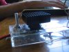
I had a question about heat: when running, the little thing gets pretty warm -- on the edge of me being able to hold my fingers to it. I have attached a heat sink (see attached pic). The NTE970 that I'm using (the "equivalent" of the LM150) is spec'ed at:

Absolute Maximum Ratings:
...
Operating Junction Temperature Range, TJ . . . .. . 0° to +125°C
Storage Temperature Range, Tstg . . . . . . . . . . . –65° to +150°C
Thermal Resistance, Junction–to–Case, RthJC . . . . . . . . 2.5°C/W
...

...although I'm not 100% of the implications, 125°C seems well above the temperature it's reaching, so I assume I'm well in the clear? I just want to make sure I don't ruin another one of these. :)

Thanks!
-c

P.s. the picture was taken by the camera being powered by the fake dowel-rod batteries from the unit. :)
 

Attachments

  • voltagereg.JPG
    voltagereg.JPG
    45.2 KB · Views: 130
The max allowed internal chip temperature is 125 degrees c. The case is probably much cooler.
The thermal resistance shows how hot its case is allowed to be at the power it is dissipating.
 
...

Hmmm... thanks, so, if I have this right:

I have 18.5 V into the thing, output to 3 V, so:
(18.5V - 3V) * 1A = 15.5W

(assuming 1A for the digital camera, which I'd guess is a fair overestimation)...

But I'm not sure how to interpret "2.5 deg C / W"?

I can also just use a lower-voltage power supply...
 
Many years ago, I purchased a wall-wart from Radio Shace that has an output voltage selector switch. You can select about 1/2 dozen output levels, starting from about 2.5V all the way up to 12V. I've never had a device since then that I couldn't power off this thing.

And it comes with a number of power connectors so it plugs right into most and DC connection jack.
 
Last edited:
You have the regulator dissipating 15.5W. Its chip to case heats with 2.5 degrees C above the ambient temperature for each Watt that it dissipates. So with an ambient of 30 degrees C, the minimum thermal resistance of a heatsink is (125 - 30)/(15.5 x 2.5)= 2.45 degrees per Watt. Select a heatsink with a thermal resistance of 1.5 degrees per Watt. It will be pretty big.
 
audioguru: did you mean 2.5 degrees / watt? Anyway, I changed out to a 5V DC adapter so now it's cool as a cucumber. I can let go of the lesson in thermodynamics, i suppose. :)

colin55: thanks, i don't intend to run any audio equipment with it...

BrownOut: yeah, the radio shack wart would be a simpler way. But I liked the challenge of the DIY, the continuously-variable output voltage, and having something to use all my leftover wall warts for. :)

Thanks all,
-c
 
Status
Not open for further replies.

Latest threads

Back
Top