Continue to Site

Welcome to our site!

Electro Tech is an online community (with over 170,000 members) who enjoy talking about and building electronic circuits, projects and gadgets. To participate you need to register. Registration is free. Click here to register now.

  • Welcome to our site! Electro Tech is an online community (with over 170,000 members) who enjoy talking about and building electronic circuits, projects and gadgets. To participate you need to register. Registration is free. Click here to register now.

knight rider led sequence

Status
Not open for further replies.

sanjubluerock3

New Member
hiii i would like to share knight rider led project including pcb layout enjoy..:)
 

Attachments

  • knight rider leds final.rar
    59.7 KB · Views: 298
  • sch-knight rider 11leds.png
    sch-knight rider 11leds.png
    57 KB · Views: 544
Any reason u didn't use a PIC?

It would allow u to create the leading/trailing LED fade in/out and use less components.
 
Years ago I did one of those circuits using what are now pretty old parts. The idea was to get the back and forth effect using a programmable up / down counter (74193) and a 4 line to 16 line decoder (74154). Rather than LEDs I used the outputs to drive transistors and automotive bulbs. Attached are the circuit and the effect.

Yeah, today a PIC would be a nice solution. I looked for a good PIC in 1982 but just could not find one. :)

Ron
 

Attachments

  • Knight Ryder Circuit.gif
    Knight Ryder Circuit.gif
    31.8 KB · Views: 2,150
  • LED Up Down Seq.gif
    LED Up Down Seq.gif
    57.3 KB · Views: 327
I thought of using pic, but i am not good at programming.I am still learning to write code so i thought i would do this project without micro-controller. I wish to do the same project using pic so can you please give me a hint on how to create the leading/trailing LED fade in/out?
 
Last edited:
Attached is some code I wrote years ago. If you learn the PIC, it is good to start with assembly language as this will teach you a disciplined way of coding that will set you up well for higher level languages.
 

Attachments

  • Knight Rider.asm
    5.7 KB · Views: 242
Algorithim

I don't have the time to do the code atm, but here is the approach.

In order to control LED brightness we use Pulse Width Modulation to control the % of on time vs off time. This is done at better than 60Hz across the whole LED bank to ensure persistence of vision.

Usually this PWM can be done by a built in option in the PIC, or you can write your own small subroutine (interrupt driven) to handle it. See the pic data sheet on this PWM.

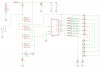
To keep things simple as this is not a production item I'd go with an 18 pin PIC to give u a decent amount of LEDs to drive at 1 per output pin. Later on u can study LED matrix addressing to conserve pins and use smaller PICs for the same job.

Basically the algorithm involves having a a RAM location for each output pin driving an LED. U make a subroutine that scans these locations and applies a pwm % to the matched output pin based on the value in the RAM location. This way you can be flexible in which ports and pins you use to create the LED bar = easier to breadboard.

Therefore 15 LEDs mean 15 ram locations in sequence will be used.

Now all that's left to be done is a timed routine to shift the values in the 15 locations (+ 6 extra, see tips below) up & down thus making the effect in the LEDs.

Tips: I'd setup the display to work with 8 as 100% brightness, 4 = 50% etc. So the ram locations for a centre glow would look like this.

0 0 0 0 1 2 4 8 4 2 1 0 0 0 0

Now your shift routine will shift these values so that the '8' bounces from the left to the right edges of your 15 cell RAM map. So u can end up with a map like this
8 4 2 1 0 0 0 0 0 0 0 0 0 0 0
or this
0 0 0 0 0 0 0 0 0 0 0 1 2 4 8

You don't want the leading or trailing 1,2,4 or 4,2,1, to be truncated with your shifting of the values, so u must place your 15 ram location map to allow for an additional 3 ram locations on either end. This totals about 21 locations which must be in sequence and free to use. Check the PIC pdf for details on the available ram.

That's about it. U can add more effects with bicolor LEDs and LED array addressing later on. With the approach discussed you can easily make a 'dual' eye system with 1 LED bank, just change the values in the 15 cell array like this:
0 0 2 4 8 4 2 0 2 4 8 4 2 0 0 , and have fun!
 
Status
Not open for further replies.

Latest threads

New Articles From Microcontroller Tips

Back
Top