Continue to Site

Welcome to our site!

Electro Tech is an online community (with over 170,000 members) who enjoy talking about and building electronic circuits, projects and gadgets. To participate you need to register. Registration is free. Click here to register now.

  • Welcome to our site! Electro Tech is an online community (with over 170,000 members) who enjoy talking about and building electronic circuits, projects and gadgets. To participate you need to register. Registration is free. Click here to register now.

"Kitt" lights with fade out...

Status
Not open for further replies.

Kitrax

New Member
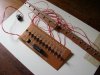
So I've made a version of the LED sequencer from Kitt (the car from Night Rider) using a 74154 decoder hooked up to a counter and a flip-flop. Everything works fine, but my teacher said it's not very authentic because the LEDs don't fade out. I figuered it was an easy fix as all I needed to do was add a capacitor

The problem is, I can't figure out how I need to be connecting the capacitor. Here's how I *think* it should work:

Code:
74154 Out (-)
   0
   |
   |
   |--------+
   |        |
   |        | 
  ---       | 
  / \ LED   | 
   |        |  
   |        | 
   |        | 
   |       === C
   \        | +
   / R      |
   \        |
   /        |
   |        |
   |--------+
   |
   |
   Vin +5V

The resistor used is a 1kΩ and the cap is a 47µF
The problem is, that doesn't work...I know I'm missing something here, but I just can't figure it out.
 
The capacitor should be across the LED. Then it will be charged slowly by the resistor and be discharged slowly by the IC.

The 1k resistor limits the current too much so the LED will be very dim. Use 200 ohms for a red LED or 100 ohms for a blue or white LED. Then increase the value of the capacitor across the LED for a longer fading time.
 
Also, it is NOT recommended to drive a reactive load directly from a logic circuit. Add a current limiting resistor in series with the circuit OUTSIDE of the capacitor.

Finally, to aid the capacitor to discharge more slowly (or to aid use a smaller capacitor), add a Shottky diode at the 74154 output. This way, the 154 will charge the capacitor but won't discharge it. The discharge current will pass through the LED which is what we want !
 
Last edited:
Finally, to aid the capacitor to discharge more slowly (or to aid use a smaller capacitor), add a Shottky diode at the 74154 output. This way, the 154 will charge the capacitor but won't discharge it.

Wait a minute...the 154 doesn't drive or charge anything...its active low, so it sinks/discharges when active....otherwise the output is seen as an open....right?

This is so aggravating...making an LED fade out *shouldn’t* be this difficult... :rolleyes:
 
Wait a minute...the 154 doesn't drive or charge anything...its active low, so it sinks/discharges when active....otherwise the output is seen as an open....right?

This is so aggravating...making an LED fade out *shouldn’t* be this difficult... :rolleyes:
It isn't. First off you are attacking it from the wrong end. The RC thing is problematic with LEDs, you might get it working, sort of, but I doubt you will be happy with the result and you will have to duplicate it for each LED.

Make a PWM circuit that works for one LED and apply it to the 154's enable pin, it will then be applied to as many LEDs as you connect to the system.

The one thing I can think of is that the LEDs, as I recall, fade in while the previous one fades out. That makes it difficult of the capacitors don't work for you. Beyond two or three light levels with diodes and resistors, if the caps don't work you will be forced into a micro in that case.

With diodes and resistors you can for any given LED you would put a diode and a resistor in to partially light the previous two and following two LEDs in the sequence. If the scan is fast enough that will repeatably fade the light in and out.

That is actually not true, the 74154 will source some, but it is not worth it to go look it up. If you get an HC154 it will source and sink 25mA.
 
another way to do it, is to link the outputs. so output 1 goes to led1 via 200r and to led2 vai 400 led 3 via 600r

then output 2 goes to led 2 via 200r, and to led 1 and 3 by 400r

etc etc
 
Make a PWM circuit that works for one LED and apply it to the 154's enable pin, it will then be applied to as many LEDs as you connect to the system.

I'm not that far in school ATM. I'm only up to Digital II, so I wouldn't know what to do with a PWM... I work for Fairchild Semiconductor, and I know we make PWMs, so if you have a particular PWM to suggest, I can get a whole mess of them for free, and possibly have someone at school (or here) help me integrate it in to the circuit.

One of the things I was wondering about, is that since the 154 has inverted outputs, couldn't I just hook the outputs up to a 7404 inverter to make the outputs going to the LED active high? :confused:
 
Last edited:
another way to do it, is to link the outputs. so output 1 goes to led1 via 200r and to led2 vai 400 led 3 via 600r

then output 2 goes to led 2 via 200r, and to led 1 and 3 by 400r

etc etc
That is what I was saying but you need the blocking diodes to prevent it from intereacting
 
Wait a minute...the 154 doesn't drive or charge anything...its active low, so it sinks/discharges when active....otherwise the output is seen as an open....right?

This is so aggravating...making an LED fade out *shouldn’t* be this difficult... :rolleyes:

The positive side of the capacitor is tied at +5 volts and the negative side is tied to the 154 output.

What happens when we active-low the pin ? It pulls down the negative side of the cap to near ground while the positive is still tied at + 5 volts. I call that CHARGING a capacitor. Ok, it's by the lower side, but it's still charging the cap !
 
I'm not that far in school ATM. I'm only up to Digital II, so I wouldn't know what to do with a PWM... I work for Fairchild Semiconductor, and I know we make PWMs, so if you have a particular PWM to suggest, I can get a whole mess of them for free, and possibly have someone at school (or here) help me integrate it in to the circuit.

One of the things I was wondering about, is that since the 154 has inverted outputs, couldn't I just hook the outputs up to a 7404 inverter to make the outputs going to the LED active high? :confused:
The PWM thing only works if you do not need more than one lit at a time and as I recall Kit the dim off and on were simultaneous.

There is no reason to invert if you use the HC154 it since the HCs drive both ways equally. You will want to do the dimming in the drive circuits for simultaneous fading. An RC to a drive transistor with an emitter resistor should work fine.
 
The KITT display was a chaser. The lights lit back and forth. Only one light was turned on at a time but since they were incandescent bulbs then they turned off slowly so it appeared to fade each bulb. The bulbs probably lighted quickly.
 
The KITT display was a chaser. The lights lit back and forth. Only one light was turned on at a time but since they were incandescent bulbs then they turned off slowly so it appeared to fade each bulb. The bulbs probably lighted quickly.
Really? I was thinking they faded in and out and that they were overlapped... It does not matter to me but it really depends on how close he wants it to the show... and if there is a difference between the old show and the new one
 
I did 20 LEDs with 64 brightness levels per LED using an 8 pin PIC and 5 transistors once... I suspect someone could code a "night rider" type back and forth fading display with it if they tried...

YouTube Video: Charlieplexed PWM-32 Demo

Mike

**broken link removed**
 
They show the new KITT lights on U-Tube. Their motion is completely different to the original one.
 
Nice little thread.

Mike your design is awesome.

Ya new knight rider version is not nicer than the original one.

I really like to build a version like Kitrax using normal components.Sure this weekend I'm going to try.

I'm tired doing those stuff with micros.

YouTube - Knight Rider Version 1.0
 

Attachments

  • Knight V1.JPG
    Knight V1.JPG
    111.5 KB · Views: 363
Last edited:
Wait a minute... I recall Futz did a type of "night rider" or "cyclon eye" with my PIC circuit... Here it is; YouTube: Bounce LED w/Fade

Is that the effect you're lookin' for?

Mike

That's *exactly* what I'm looking for! :D However...just not in PIC form. I planning on making it into a PIC, but that class is still 2 years away.
 
Hmmm How about this?

Hey Kitrax,

I did this for a brake light mod to my motor cycle.

Evil Mad Scientist Laboratories - Make A Cylon Jack-O-Lantern

I'm at work so I can't reach youtube to see what Futz project was. :(

Well maybe this will help a little. After a while those LED's stay charged and don't go off all the way. I'm not sure if that was the design or maybe my ground is not that good.

ted
 
Last edited:
Hey Kitrax,

I did this for a brake light mod to my motor cycle.

Evil Mad Scientist Laboratories - Make A Cylon Jack-O-Lantern

I'm at work so I can't reach youtube to see what Futz project was. :(

Well maybe this will help a little. After a while those LED's stay charged and don't go off all the way. I'm not sure if that was the design or maybe my ground is not that good.

ted
Now that's funny... just exactly what I suggested - an RC on each output of the 4017 driving the bases of the LED drive transistors. Go figure!
 
Status
Not open for further replies.

Latest threads

New Articles From Microcontroller Tips

Back
Top