Continue to Site

Welcome to our site!

Electro Tech is an online community (with over 170,000 members) who enjoy talking about and building electronic circuits, projects and gadgets. To participate you need to register. Registration is free. Click here to register now.

  • Welcome to our site! Electro Tech is an online community (with over 170,000 members) who enjoy talking about and building electronic circuits, projects and gadgets. To participate you need to register. Registration is free. Click here to register now.

KitchenAid KBMS1454SSS-3 Microwave Control Board Level Repair Help Request

Status
Not open for further replies.

wickline

Member
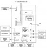
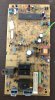
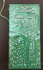
I have a KitchenAid KBMS1454SSS-3 Microwave for which the control board is not operating either the cooling fan or the turntable motor. The turntable motor and cooling fan bench test as both being operable pointing to the control board as the culprit of the malfunction. Attached diagram of the control board connections indicate both cooling fan and turntable connect to the board at connector P2. I would like to attempt to repair the board however I don't have a schematic for it. I'm comfortable removing and replacing components but I could use some help knowing what to suspect as the most likely point of failure. I don't see any obviously failed capacitors. I'm a neophyte not a trained electronics technician so I welcome any help available in being able to trace where in the circuit to look. I can de-solder, purchase (may need help identifying what on smallest items), and reinstall components but that's about it. I'm also including pictures of the front and back of the board to facilitate giving me advice on what to do next. The board part number is 8231 280 11363 in case anyone can locate a schematic with parts list - that would also help greatly as I find it difficult to identify the replaceme
 

Attachments

  • ControlBoard_20191128.JPG
    ControlBoard_20191128.JPG
    52.1 KB · Views: 428
  • BoardFront.jpg
    BoardFront.jpg
    995.9 KB · Views: 280
  • BoardBack.jpg
    BoardBack.jpg
    1.1 MB · Views: 238
I would start by checking if the coils on the turntable and fan relays are being energised when you expect them to be. To do this I would solder some wires to the relay coil connections and bring the wires out so you can safely test the voltages. The relays will probably be driven by a relatively low DC voltage . (12 or 24 volts. ?) The relays will probably be marked with their operating voltage. From this test you will know if you are looking for a fault on the drive side of the relays or the contact side.
I am assuming everything else works as it should.

Les.
 
As Les says, check if the relays are switching - if the motors aren't going round you should be able to hear them click.

But apart from that, as a microwave oven service engineer for a few decades, such a fault on the control board would be almost entirely unknown - they just don't happen.

It's MUCH more likely to be a fault off the board, probably one of the interlock switches, or even a thermal fuse.

And while you don't have the circuit for the PCB (they don't usually provide them, or any spares for them), it's pretty universal that the circuit for the complete oven (showing the interlock switches and fuses) is stuck inside the lid. By referring to that you should be able to spot what could cause the problem - and it's a fairly common one.
 
The reason for making the comment about everything else working was to more or less eliminate an interlock problem. I would imagine the first thing the interlocks would prevent working is the high voltage power supply for the magnetron.. If the relay coils are being driven then check the supply side of the relay contacts and assuming the relays switch the live then check the neutral connection to the fan and turntable motors.

Les.
 
Sorry - my description was somewhat lacking as to why I suspected the control board - first I confirmed the 3 door interlock switches are functioning properly through open and closed door continuity tests with those switches disconnected from the circuit (while installed in microwave). Operationally I placed a container of water in the unit, set cook time for 3:00 minutes, and the microwave ran heating the water (turntable not turning) until there was 9 seconds left on the count down time at which point I could hear the magnetron stop humming. The reason the magnetron stops is because the cooling fan wasn't running (didn't realize that when conducting the test) causing the magnetron thermostat to open and stop operation of the magnetron. I will give Les's suggestion a try unless anything else in my description leads to the belief to look elsewhere besides the control board. Thanks for the feedback - I'll add to the post after completing the test.
 
I'll repeat again - check the circuit inside the lid, you should be able to see what could cause the issue - it's almost certainly not on the PCB, the chances are EXTREMELY small.

As I mentioned before, this is a very common fault, and I've never seen one yet that was a fault on the PCB.
 
Thanks for the advice Nigel. I did verify the interlock switches (previously mentioned door open / closed tests) and cavity thermostat (continuity at ambient temp) were all functioning properly. Since the magnetron engages (and overheats due to the fan not operating) I'm not sure where else I would look for a cause of the fan and turntable not operating while these individual components pass resistance checks. I'm attaching what I've located on the internet as to what I believe is the appropriate tech data sheet this unit (tech data sheet renamed to my model number - not the original filename). Unfortunately the tech data sheet is not with the unit - I can see the plastic wrapper it would have been contained in but someone prior to me has separated it from the unit. I should mention that the one I'm attaching indicates presence of inverter power supply - that is not the case with this unit - it has the high voltage transformer, capacitor, and diode. Where else would you have me look off board besides the tests I've already done? Again, I appreciate the guidance very much - it's got me stumped. I've been unable to upload the service manual I found due to file size.
 

Attachments

  • KBMS1454SSS_TechSheet.pdf
    511.8 KB · Views: 223
According to that diagram, the motors are switched in the neutral wires, and the neutral connects to pin 2 of connector P1. and the switched sides of the two motors are pins 1 & 3 of P2 - so measuring from P1 pin 2 to either Pins 1 or 3 of P2 should be 120V (AC) with the oven not running, and should drop to zero when you press cook.

So what do you measure under those two cases?.
 
I don't get any significant voltage between P1 pin 2 to P2 pin 1 or 3 with the unit plugged in and not running.
 
I get about 122 V with the unit plugged in and not running. Once I hit start the voltage drops to about 115 - same results on either.
 
I suspect the drop from 122 V to 115 V is due to the mains supply sagging under load. (You could confirm if this is the case.) Is the cavity light working ?
BoardBack_2.jpg

The above is a mirrored version of the track side of the board so it is easier to match up with the component side. I suspect the track I hasve drawn a red line on is the neutral feed from 2P1 to the contacts of the 3 relays. Inspect the three solder joints marked in red as I thing these are to the relay contacts. I think the neutral must be getting to this track as I think the two diodes at the top of the track supply the switch mode power supply for the electronics which must be working.

Les.
 
The cavity light is working - both on door open and on start of cooking cycle. I'm waiting to hear from back from Nigel before proceeding to pull the board out again to check those solder joints. Thanks Les!
 
I think the most likely PCB components to fail, (if there is no problem with the interlock switches or bad PCB solder connections), for the symptoms you are describing, would be one, or both of the relays failing. You can either check for DC voltage across the relay coil winding terminals (relay 4906=turntable & relay 4901=fan) by probing them with a VOM, or feel or listen closely to the relays to see if they are clicking on when they should, by putting one end of a long wooden dowel (or other insulated) item between one of the relay covers, and the other end of the dowel against that little nub of your ear, that protrudes out and over the opening to your ear canal, pushing it in to close off the ear canal. Your hearing in that ear will become muffled, but you will clearly hear the relay click on, that the other end of the dowel is in contact with. Although you may hear the relay click on, the relay 110v contacts may still be burnt or otherwise be defective; but you will surely know that the other electronics is triggering, or firing the relays on. I would also carefully check those two relays' solder connections, by resoldering them to be sure. Have you actually applied 110v directly to the fan & turntable motors, (after unplugging them from their PCB connectors), to be sure the motors actually turn, and are not just frozen mechanically by hardened grease or by dirt or other debris somehow? There usually is plenty of greasy grime that gets circulated around inside of a microwave oven by the fan, due to steam coming off of the food or beverage; also collecting dust and dirt. Otherwise, trace and check all wiring for continuity thru all plugs and connectors to the relay contact terminal solder connections.
 
I would also consider resoldering all of the P2 connector PCB connections, (although it is hard to see), it appears that some of the upper connections towards the center of the PCB, (which are for the turntable & fan), may have some minor cracks in the solder joints in one of your two photos.
 
The cavity light is working - both on door open and on start of cooking cycle. I'm waiting to hear from back from Nigel before proceeding to pull the board out again to check those solder joints. Thanks Les!

According to the circuit you posted, the cavity light and cooling fan are wired almost identically across the same points, the only difference been the separate relays.
 
I tried listening for the relay clicks on the fan and motor but the relay that engages the magnetron transformer is so strong it's hard to tell if the vibration I'm getting is coming from the fan / motor relay or if it is secondary vibration from the magnetron transformer relay. I pulled the board and did a continuity check from the pin nub Les indicated to elsewhere on the ground plane and it shows continuity. If I pull these two relays off the board can I just test them applying 12 V DC across the coil to see if the click or not? Attached is the data sheet for the SDT-S-124LMR relays that these are.
 

Attachments

  • SDT_S_124LMR_Relay.pdf
    606 KB · Views: 208
I tried listening for the relay clicks on the fan and motor but the relay that engages the magnetron transformer is so strong it's hard to tell if the vibration I'm getting is coming from the fan / motor relay or if it is secondary vibration from the magnetron transformer relay. I pulled the board and did a continuity check from the pin nub Les indicated to elsewhere on the ground plane and it shows continuity. If I pull these two relays off the board can I just test them applying 12 V DC across the coil to see if the click or not? Attached is the data sheet for the SDT-S-124LMR relays that these are.

You could, but it might be easier than that.

In the middle of the board there are four transistors, 7903, 7906, 7901 and 7902. These are the drivers for the four relays, with 7903 the one feeding the magnetron relay. The collectors of these transistors are all at the top, so you should be able to get your (red) meter probe on to them fairly easily, with the black probe connected to chassis. With the oven not operating all four collectors should be at 12V, and all should go low (close to zero volts) when you press start.

If they don't go low, then the relays aren't been switched ON.

As a safety procedure, I would suggest unplugging the wires on the top of the magnetron relay (or one of them), this will prevent the magnetron over heating (due to no fan) and remove the fatal high voltages around it.
 
I also agree that this is the way forward. (An alternative way to do what I suggested in post #2.) Nigel's practical experience with microwave ovens was a a good reason to think it was unlikely to be a board fault but it is now looking like in this case it is a faulty board. It would be interesting to know if the fan and the turntable stopped working at the same time as I can't see any single fault that would cause both to stop working.
The nearest thing I can see to something that would stop both relays working is the wire link 9904 which I think connects the emitters of transistors 7906 and 7901 (I think these are the two transitors that drive the relays. ) to the DC supply ground. I think the DC ground is also connected to the green/yellow earth wire on the board. Before doing the test with power on you could do a continuity test from the earth wire to the wire jumpers 9901, 9903 and 9904.

Les.
 
Last edited:
Status
Not open for further replies.

Latest threads

New Articles From Microcontroller Tips

Back
Top