Continue to Site

Welcome to our site!

Electro Tech is an online community (with over 170,000 members) who enjoy talking about and building electronic circuits, projects and gadgets. To participate you need to register. Registration is free. Click here to register now.

  • Welcome to our site! Electro Tech is an online community (with over 170,000 members) who enjoy talking about and building electronic circuits, projects and gadgets. To participate you need to register. Registration is free. Click here to register now.

keyboard encoder

Status
Not open for further replies.

PG1995

Active Member
Hi,

Please have a look on this attachment.

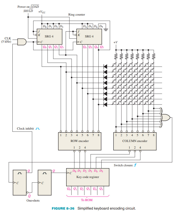
It says, "When a key is closed, the two one-shots produce a delayed clock pulse to parallel-load the 6-bit code into the key code register. This delay allows the contact bounce to die out. Also, the first one-shot output inhibits the ring counter to prevent it from scanning while the data are being loaded into the key code register."

The clock pulse is fed to both serial registers or ring counter through an AND gate. One input into the AND gate comes from a clock and the other comes from one-shot on the left. For the clock pulse to pass through AND gate, the input coming one-shot should normally be HIGH.

Question:
Is the one-shot on left produce HIGH-to-LOW pulse when triggered? What about the one-shot on right? Thank you for your help!

keyboard_encoder_diagram-jpg.117684
 

Attachments

  • keyboard_encoder_diagram.jpg
    keyboard_encoder_diagram.jpg
    114.1 KB · Views: 1,095
  • keyboard_encoder.jpg
    keyboard_encoder.jpg
    416.4 KB · Views: 323
The waveforms are shown on the monostable symbols and in blue against the line going upwards from the left hand one.

The output from the Q pin is a short positive pulse.
(The actual duration depends on the timing components used, which are not shown).

The /Q gives the inverse, a negative going pulse. The end of that (the rising edge) triggers the second monostable.

Edit:
To clarify terminology, a "pulse" is a double transition - low to high then high to low, or the opposite.
A single change either way is an "edge" - as in the signal from the 8 input gate to the first monostable, the only important part of that is the negative to positive transition, a positive edge, as shown in blue.
 
Thank you!

The waveforms are shown on the monostable symbols and in blue against the line going upwards from the left hand one.

The output from the Q pin is a short positive pulse.
(The actual duration depends on the timing components used, which are not shown).

So, it's a short positive pulse, LOW to HIGH transition, from the one-shot on left and it flows from Q toward the AND gate. It'd mean that normally the line is LOW. The AND gate has two inputs; clock input and input from Q. If the line from Q to AND gate is normally LOW then the AND gate won't let clock signal to pass through. But it shouldn't be so because clock signal needs to pass through to make the circuit work. Where am I going wrong? Thank you for your help.
 
Where am I going wrong?
You are not - you have it absolutely right, the diagram is inaccurate.

The inhibit would have to be taken from the /Q, so it's normally high and pulses low, for the clock inhibit gate to work...
 
Status
Not open for further replies.

New Articles From Microcontroller Tips

Back
Top