Continue to Site

Welcome to our site!

Electro Tech is an online community (with over 170,000 members) who enjoy talking about and building electronic circuits, projects and gadgets. To participate you need to register. Registration is free. Click here to register now.

  • Welcome to our site! Electro Tech is an online community (with over 170,000 members) who enjoy talking about and building electronic circuits, projects and gadgets. To participate you need to register. Registration is free. Click here to register now.

Junebug Problem

Status
Not open for further replies.

3v0

Coop Build Coordinator
Forum Supporter
I have 3 Junebug boards with a strange problem. Other boards constructed at the same time work fine.

Three or four seconds after the USB cable is inserted the inductor gets hot. This happens with the 2550 in place or not. With the 2550 in place the yellow connect light comes on.


Q1 is a Farchild 2n3904CTA. The inductor does not heat with it removed. Replaced one but it did not help.

Any ideas ?

---------------------------------

also

Another route to ground for the inductor is via D1 R3b and R6. It checks out as expected and is too much resistance to allow enough current to flow to heat the inductor.
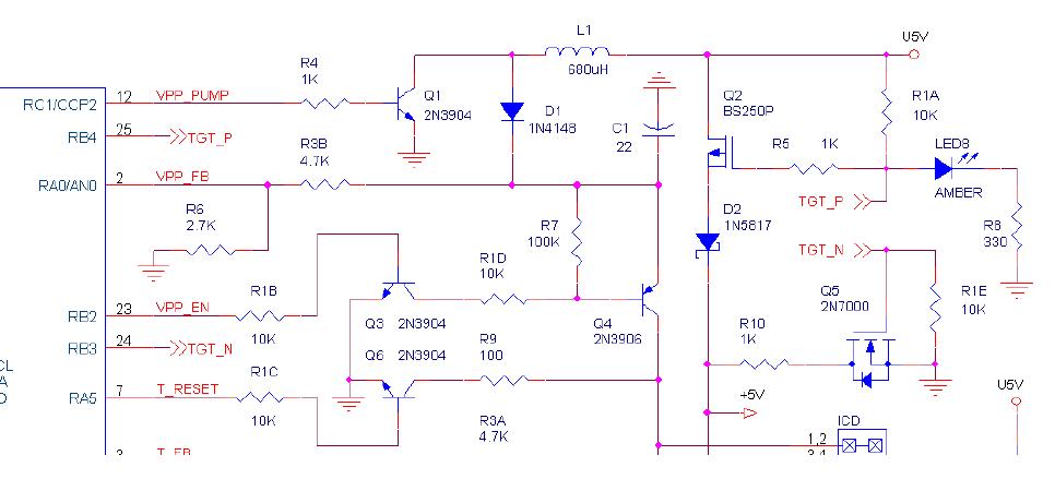
osc2-jpg.25191


3v0
 

Attachments

  • osc2.jpg
    osc2.jpg
    51.8 KB · Views: 390
Last edited:
R4 should have a square wave across it, if it's high Q1 will pretty much act as a dead short. The PK2 test software should allow you to turn on the boost converter in VPP test mode. Make sure the VPP voltage divider is ok R3B, R6.
 
My scope shows R4 low on a good unit when VPP is inactive. On the problem units it is the same. By the time one does a check-communication and goes into troubleshoot the inductor is already HOT. The VPP test says short but that is not great suprise. It shuts down the pump through R4 quite fast. Not useful for this or finding shorts.

The problem is that the off state is conducting current through the inductor.

I checked out the voltage divider circuit as noted in my original post.

R4 should have a square wave across it, if it's high Q1 will pretty much act as a dead short. The PK2 test software should allow you to turn on the boost converter in VPP test mode. Make sure the VPP voltage divider is ok R3B, R6.
 
I changed the colours of the LED's (program side) my PIC is getting hot never try to change their resistors:D

Bill do you recommend to bypass the 2N7000 & BS250 when I get this error?

"PICkit 2 VPP voltage level error. Check target & retry operation".
 
If I remember, the inductor should have a current carrying capacity of 20mA at least. Also why not a 1N5819 for the diode D1 that follows. Perhaps it helps in improving the efficiency of the Vpp generator. At times these inductors go partially short. Of course you have indicated that you swapped it.

I may also suspect a leaky Transistor Q1.
 
Last edited:
What about adding a 100k resistor across Q1 B-E to make sure it stays closed while RC1 is input during init (although it is short time i guess :rolleyes: )
 
qratman & mvs sarma,

I have constructed at least 15 working Junebugs using Bill's boards. The circuit works as designed.

This fall I built a batch of 7, these 3 had the HOT inductor.

I did not change the inductor. But I can test the inductiance with my superprobe in the AM. Could be the ones that got HOT shorted as you say and they need to be replaced. Buy why did they get hot ?

I am quite sure I made some error but it eludes me. If nothing else I will breadboard the charge pump to test the parts the place them on the boards.

3v0
 
Last edited:
hi 3v0.
I suspect you may have already looked at these possiblities.

Q1, s/c or incorrect pinning
C1, s/c or reversed
Q1. s/c
SW6 bit open

Track whiskers along L1 > D1 > Q1 collector ,, to adjacent tracks.
ditto.. D1 cathode>C1 +V > Q4 emitter.

As 7 out 10 work, its most likely a whisker on the other 3.:)
 
Erick,

Q1, s/c or incorrect pinning (checked)
C1, s/c or reversed (checked)
Q1. s/c (same as 1?)
SW6 bit open (only switch installed in the boot sw 5,​

You may be right about the wiskers but i have learned to check my own work many time prior to putting the blame on faulty parts. :)

I constructed all the boards in this run assembly line style. Grab a part and put in on all boards then move on to the next. Execpt for putting a transistor in backward that should reduce the change for placement errors. The programmer section was populated then tested. The failed and the tutor section was not populated.

I removed Q1 and the heating stoped. That tells me there is not short between E C. My scope shows R4 low on a good unit when VPP is inactive, same on non working units. Transistors are not my strong point. But is seems to me that if Q1 has a low base there should be no base emitter flow.

I did switch transistors mid run. The new ones are packaged as Farchild 2N3904CTA. The actual transistor is stamped 2N3904CJ22. But if I recall some of the units with the new transistors worked. Not 100% on that. Did not find any info on the stamped number.

3v0
 
Sounds like it is the pin out of Q1. Where some TO92s have the center lead as the base; others have the center lead as the collector.
 
Sounds like it is the pin out of Q1. Where some TO92s have the center lead as the base; others have the center lead as the collector.

Some times I need to be told the same thing a few times to get it! The ohm meter says you are right. I expected either EBC or CBE, I was thinking I had a bad batch of transistors.

I did a bit of fancy work and managed to get on of the stupid thing mounted. Works like a champ.

The data sheet that matched the part number on the anti-static bag did not match the part in the bag. Go figure. I wonder if I may give Mouser a call.

I am glad there is only one per board.

3v0
 
Last edited:
There are 3 NPN transistors on the board, how were the other ones not affected? I've built some Junebugs with PN2222 as I've got hundreds of those.
 
  • Like
Reactions: 3v0
Bill,
Yes they were! :eek: Changing Q1 only fixed the charge pump. Q3 and Q6 needed to go too. I had it in my mind there were 1 2N3904 and 3 2N3906. Sort of humbling.

The programmer section on one now works.

+5 from Junebug to target is as low as 4V on some units. It is not enough to power the LCD. Maybe I can figure that one out. :) If not I can replace the transistor with a jumper.

Thanks Bill
3v0
 
I expected either EBC or CBE, I was thinking I had a bad batch of transistors.
The data sheet that matched the part number on the anti-static bag did not match the part in the bag. Go figure.
I've noticed that Japanese and far east transistor manufacturers tend to like the ECB pinout for To92s where as the North American manufacturers tend to go with the EBC pinout.
Good to see you got it working. :)
 
There are all up and working.

I talked with a tech rep at Mouser. I was not the only one messed with with the pinout on this transistor. They have added a line to description

Small Signal Transistors NPN Trans Gen Purp Collector=Middle Pin​
The parts still points to the wrong datasheet but they are working on that. Credited back the cost of the parts too. :rolleyes:

I am still a bit confused about the same part number including sufix having different pinouts.
 
I am still a bit confused about the same part number including sufix having different pinouts.

Are you new? :D

It's been a common problem for years, different manufacturers using different pinouts for supposedly the same transistor. Watch out for 2N3819 FET's, they seem pretty random on the pinouts.
 
I do very little analog. I used to have people for that. :)
EDIT: There were call EE's.

Are you new? :D

It's been a common problem for years, different manufacturers using different pinouts for supposedly the same transistor. Watch out for 2N3819 FET's, they seem pretty random on the pinouts.
 
Last edited:
Status
Not open for further replies.

Latest threads

New Articles From Microcontroller Tips

Back
Top