intensenex
New Member
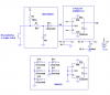
I am really having trouble with my dual JK flip flop 4027bp
I have all my connections right and inspite of that i get output as high from all pins. And not only that, at times the voltage is swaying from 3v to 5v. (Battery is a little down so i am getting 5V)
here is my circuit diagram
**broken link removed**
I have built the same circuit and the output never goes down upon playing with the switch infact i even get output from the second flip flop pin on the left side of the IC. Also sometimes output goes around 10V wen i connect the Vcc back again.
i have hopelessly give up for now. i think my IC is messed up.