Continue to Site

Welcome to our site!

Electro Tech is an online community (with over 170,000 members) who enjoy talking about and building electronic circuits, projects and gadgets. To participate you need to register. Registration is free. Click here to register now.

  • Welcome to our site! Electro Tech is an online community (with over 170,000 members) who enjoy talking about and building electronic circuits, projects and gadgets. To participate you need to register. Registration is free. Click here to register now.

Issue with Single Phase to Single Phase Cyclo converter Circuit.

Status
Not open for further replies.

Hamidnawaz340

New Member
HI,
I am new at this forum.

I am trying to make a circuit for single phase to single-phase cyclo converter. Using Pic Micro Controller for Triggering Gate of Trails.

Triac ->
Optocoupler ->
For Trigring Triacs -> PIC Micro controller.

I was unable to find any circuit diagram with the Triac Driver part. After some experiments I found a method to trigger Triacs. The Problem When I try to Operate each bridge (Positive and Negative) separately both work fine but when I combine two Bridges in anti-parallel the fuse blows out.
I have checked much time, there is no shortage. Maybe I am not making the right circuit.

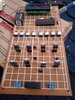
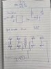
I am Using a 100 Watts Bulb at output and I don't have osciloscope available, I am not able to share output waveform. I have attached the circuit diagram of what I have made, I there is an issue with the circuit please suggest me the right circuit. Thanks
 

Attachments

  • Circuit Build.jpeg
    Circuit Build.jpeg
    158.8 KB · Views: 210
  • Circuit Diagram and Driver Circuit.jpeg
    Circuit Diagram and Driver Circuit.jpeg
    137.9 KB · Views: 272
There is nothing wrong in principle with the configuration you are using, that's how bidirectional thyristor drives work.

The likely causes of problems I can think of are either not leaving enough time for thyristors in one bridge to turn off, or the lack of "snubber" components to limit the rate-of-change across other thyristors when some switch on.

Are you using the AC zero crossing to synchronise the thyristor firing control with the AC cycle?
You need to either do that and wait until after a zero before triggering different thyristors, or leave more than 10mS so any previously triggered have switched off at a zero crossing.


For snubbers, add four R-C networks, eg. 0.1uF and 100 ohms in series, connected from each AC in to each DC out point.

Thyristors can trigger spontaneously if the voltage across them changes too fast, due to internal capacitance from anode to gate etc., the Dv/Dt parameter in the data - as low as 50V per microsecond for the ones you are using, without a gate-cathode resistor. Snubbers slow the rate of voltage change, as well as reducing interference and improving switching in the case of an inductive load.

Adding eg. a 150 Ohm resistor between gate and cathode on each thyristor may be a good idea, it is recommended in a lot of applications.
 
I am Switching on the second bridge after an 11ms delay, and I will try to add an RC network.

One more thing I noticed is about Optocoupler. When AC input is given to the circuit, Optocoupler Misbehaves some time (indicated by LEDs on the DC side).
Have you checked the Optocoupler connection? Maybe my Triac driver circuit is the reason.
 
Please, when you draw a schematic diagram, use the correct symbols for the components.

A Triac symbol is not a rectangle with dots.

As it stands, your schematic appears to have an error, but without the correct symbols, I can’t tell for sure.
 
Status
Not open for further replies.

New Articles From Microcontroller Tips

Back
Top