Electro Tech is an online community (with over 170,000 members) who enjoy talking about and building electronic circuits, projects and gadgets. To participate you need to register. Registration is free. Click here to register now.
Welcome to our site! Electro Tech is an online community (with over 170,000 members) who enjoy talking about and building electronic circuits, projects and gadgets. To participate you need to register. Registration is free. Click here to register now.
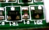
seldom to see the value printed using colour bands. That one has a resistance of 270,000Ω or 270KΩ. The black markings are just spacings between value numbers.
seldom to see the value printed using colour bands. That one has a resistance of 270,000Ω or 270KΩ. The black markings are just spacings between value numbers.
First thanks for clarifying what it is, but why use a mini-melf what on same board they use 0805? it measures 269R (not 270k) I have read that some mini melfs are very high precision could this be why it's used?
First thanks for clarifying what it is, but why use a mini-melf what on same board they use 0805? it measures 269R (not 270k) I have read that some mini melfs are very high precision could this be why it's used?
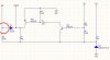
I don't think it's power, this is a RS232 two wire (Tx+RX) to 1 wire circuit so there is no real power going through it (or am I wrong!), I have managed to create a schematic for this circuit as I also wanted to know if it's possible to stop the TX comming back down the RX line by somehow chopping the line somewhere around point with red circle around it.
My thinking is that every time a TX pulse is sent use this to disable the RX line, any ideas anyone?
Power considerations would be the only reasons I would choose a mini melf resistor instead of a 0805 resistor there. R1 biases the 5.1V zener diode; depending on the value of Vcc, there could be a few milliamperes flowing through R1, hence the need of a higher power rating. Do you know that value?
On a side note, 0805 reistors are usually very precise (a tolerance of 0.1% is common). But that's not a requirement for R1.
seldom to see the value printed using colour bands. That one has a resistance of 270,000Ω or 270KΩ. The black markings are just spacings between value numbers.
Power considerations would be the only reasons I would choose a mini melf resistor instead of a 0805 resistor there. R1 biases the 5.1V zener diode; depending on the value of Vcc, there could be a few milliamperes flowing through R1, hence the need of a higher power rating. Do you know that value?
On a side note, 0805 reistors are usually very precise (a tolerance of 0.1% is common). But that's not a requirement for R1.
Not necessarily. The precision of the resistor has nothing to do with it's size, as you well know. Most 0805 resistors have typical tolerances that you would see with their carbon-film axial leaded cousins. The most common tolerance for resistors is 5%. This holds true for SMD resistors as well.
True, but 1% metal films are about as good as you can commonly get cheaply in an axial package. In a chip package, you can get .5% about as cheap. Chips go even more precise (.1%, .05%, .02%), way more precise than the common axials, but it gets progressively more expensive. By the time you get to .02% they're horribly expensive.
FWIW, Yageo 1% axial metal films and Susumu 0.5% 0805 thin film chips are what I keep in my stock bins.
SMT capacitors is where we can really talk about both price and performance benefits over their leaded brethren, but that is for another thread
I get 176.3mW. 0805 resistors are rated for 1/8th (125mW). So that may be why they went with a melf here. But the next size up, 1206, is rated at 3/4W. So they could have easly have used this with no real estate constraints. It would cost less as well.
True, but 1% metal films are about as good as you can commonly get cheaply in an axial package. In a chip package, you can get .5% about as cheap. Chips go even more precise (.1%, .05%, .02%), way more precise than the common axials, but it gets progressively more expensive. By the time you get to .02% they're horribly expensive.
FWIW, Yageo 1% axial metal films and Susumu 0.5% 0805 thin film chips are what I keep in my stock bins.
SMT capacitors is where we can really talk about both price and performance benefits over their leaded brethren, but that is for another thread
That's correct, of course. I was exactly pointing out that 0805 resistors can be as precise as mini-melf resistors - regardless of the size, as you say - in response to this question:
Scarr said:
I have read that some mini melfs are very high precision could this be why it's used?
So, precision was not the reason to choose a mini-melf resistor for R1; instead, that choice was caused by power dissipation as I supposed and as it's demonstrated by your calculations. A 1206 resistor rated for 0.75W would have been just fine.
P.S.: from my experience, the most common tolerance for 0805 resistors is 1% in the industry.
This site uses cookies to help personalise content, tailor your experience and to keep you logged in if you register.
By continuing to use this site, you are consenting to our use of cookies.

")