Continue to Site

Welcome to our site!

Electro Tech is an online community (with over 170,000 members) who enjoy talking about and building electronic circuits, projects and gadgets. To participate you need to register. Registration is free. Click here to register now.

  • Welcome to our site! Electro Tech is an online community (with over 170,000 members) who enjoy talking about and building electronic circuits, projects and gadgets. To participate you need to register. Registration is free. Click here to register now.

Is this a three leg capacitor?

Status
Not open for further replies.
Pfaff 1222E Running slow.

Hi Guys,

I have a PFAFF 1222E with some elec issues.

Motor is running slow.

Disconnected the drive belt so no load on the motor.
The foot pedal does not vary the speed. Not until it gets to the end of the travel does the motor start and it runs relativly slow.

Check the pedal - 120K linear pot. Very end is about 1 Ohm.
Seems to work ok.
Shorted the leads coming in to the pedal, motor ran at the same slow speed.

(An idea of the speed, it take about 2 seconds for the needle to complete one cycle.)

There is about 4.5Vac across the foot pedal leads.

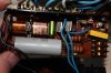
Cleaned the commutator. Have not checked the brushes.

A completely broken machine would be more helpful. This half broken problem is a bit tricky.

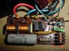
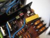
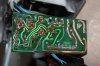
PCB looks good. I replaced the BRY39 tranny as a pot luck guess. No change.

Any thoughts?
Would a bad resistor cause a fault in a voltage divider perhaps and limit the speed?

The motor looks like a right pain to take out, hence not checking the brushes.

Cheers,

Waycon
 

Attachments

  • 06-10) IE - Pfaff Sweing machine - 1008142023 - 017.jpg
    06-10) IE - Pfaff Sweing machine - 1008142023 - 017.jpg
    3.7 MB · Views: 2,803
  • 06-10) IE - Pfaff Sweing machine - 1009091622 - 027.jpg
    06-10) IE - Pfaff Sweing machine - 1009091622 - 027.jpg
    3.5 MB · Views: 2,214
  • 06-10) IE - Pfaff Sweing machine - 1008142022 - 015 (Large).jpg
    06-10) IE - Pfaff Sweing machine - 1008142022 - 015 (Large).jpg
    212.7 KB · Views: 1,810
My thoughts on Waycon's slow speed trouble.

Hi Waycon,
You obviously have electronic problem since motor runs and responds to foot control.
Please study my schematic reposted 18 May 2013.
See microswitch on pins 7, 8, & 9 at lower right side. it changes motor speed from foot control to fixed, 'very slow', for the 'needle up or down' function. First up, I wondered if you have this microswitch permanently in 'Slow' position. That's about how fast it goes in that function.
Thinking again, this is not logical.
Check resistors around the centre of the schematic and 22 volt Zener. Some of them will cause this symptom.
Change both 33K 1watt resistors for new (modern) ones. Originals are real duds!
Check the 1K, 10K, 12K & 15K resistors. New ones there won't hurt either.
If the 22 volt Zener went low voltage, what you see will happen.
Here are the connection and schematic diagrams again.
Regards.
Clive Judd.
 

Attachments

  • Pfaff 1222 body wiring.png
    Pfaff 1222 body wiring.png
    394.1 KB · Views: 2,390
  • Pfaff 1222 motor control.jpeg
    Pfaff 1222 motor control.jpeg
    1.3 MB · Views: 7,100
Thanks Electro,

You are right about the microswitch. It is working normally and when opened the motor runs a bit slower.
I will let you know how I get on after I change the resistors. One resistor measured 0.9MΩ and the other 60MΩ. I would call that o/c really.
Would it be worth increasing the wattage of the resistors?

Thanks again,

Waycon
 
Hi waycon,
Looks like you are on the right track!
Those resistors were 'carbon composition' types, on the boards I have seen. Probably are from 1960/70's and way beyond their use by date.
Manufacturers in mid 1960's, quoted aging typical positive drift of 2 percent per annum! Little wonder you get those readings.
Little value in putting larger wattage types. Use modern metal film or similar types.
One thing to watch with some resistors is the voltage rating. Some small metal film resistors are only 250 volts maximum.
Those two 33k 1 watt resistors need to be say, 400volt rated, as they see a lot of the line volts across them. These old, 1 watt types had the higher voltage rating back then.
I guess each 33k resistor will dissipate less than 0.5watt, so bigger wattage is a waste of time.
Keep up the good work. Pfaff 1222 machines are a great product.
Regards,
Clive Judd.
 
Sorted:

Changing the 33K resistors worked. System runs a lot faster.
I measured a few voltages whilst I had it exposed. 86Vdc across the 33K, and boy do they get hot. Holding a thermocouple next to the resistor it gets to 70 DegC fast. This feels a little too hot. It is no wonder that the old carbon resistor burnt out. I changed a few other resistors but the values of the old ones were within 10%. It would feel better if these resistor were running not so hot. Perhaps there are other issues. A 5W resistor might disapate the heat better.

Anyway thanks for the pointer Electro Clive,

Waycon
 
Hi waycon,
Glad to hear your success so far.
Regarding heating of 33K resistors, couple of things to remember when assessing the resistor dissipation.
First, when sewing machine is operating, it spends short time 'On' & longer times 'Off'. Average heating over time is quite low.
Next, 86 volts you measure is inaccurate, unless you use 'True RMS' style DVM. I believe wave-form is not sinewave on that part.
On your figures, 33K is dissipating only 0.224 watts! Does not seem a worry.
I would say, 70 DegC, is not very hot, measured on surface of 1 watt resistor. However choose what component will fit in the space.
Clive.
 
hello guys,
I'm sorry for my bad English ...
I have a Pfaff 1221, the control board is the same as on page 1. I had the same problem, the capacitor is blown and the fuse is broken. the capacitor they told me to remove it and not replace it, because it should work the same. I changed the fuse, the machine turns on, the light is ok, pressing the pedal the engine does not work. What can be broken in the circuit? can you help?

Thank you.
 
hello guys,
I'm sorry for my bad English ...
I have a Pfaff 1221, the control board is the same as on page 1. I had the same problem, the capacitor is blown and the fuse is broken. the capacitor they told me to remove it and not replace it, because it should work the same. I changed the fuse, the machine turns on, the light is ok, pressing the pedal the engine does not work. What can be broken in the circuit? can you help?
Thank you.

Hi Kenny80,
Your English looks good so far.
Your post seems to show that you have little electronics knowledge. Please don't be insulted.
Internet searches will attract everyone, whatever their knowledge. This forum collects members, who commonly have some electronics knowledge.
Regarding the Pfaff 1221.
Advice on the capacitor is right, basically.
Capacitor exists to control Radio-frequency interference(RFI) generated by motor operation and OK to remove it if you are not concerned by 'noise' in your stereo sound gear or radio receivers.
Suitable noise suppression capacitors are available, from professional electronics suppliers.
Many parts can cause your motor to stop. It is not possible to make useful suggestion without testing.
An Electronics Technician can do tests if you are not able.
You need to test some things with multimeter if available.
I will now suggest some basic tests that you or technician can perform.
1. Disconnect machine from power. MOST IMPORTANT!
2. Check for broken wires from the machine plug to foot pedal.
Set 'Ohms' range on multimeter. Remove plug from power/pedal at machine. Connect multimeter probes between two pins opposite key-way, on cord plug.
Test for operation of Foot Pedal. Should read between Zero and 20 thousand Ohms approximately, as pedal operates.
3. Get access to the terminals of the Motor Control Board.
Set 'Ohms' range on multimeter. Test between terminals 4 and 5 (Motor power connections) on 'Motor Control PCB'. Should be less than 100 ohms.
If very high ohms or 'open circuit' motor will not work.
Most common cause is worn brushes. Motor is difficult to remove. Go to professional Sewing Machine Technician.
4. If above test (3) is OK, electronic control board may be faulty.
Basic test for Motor Control Board follows.
5. Set multimeter range to more than 250 volts AC.
Connect machine to power and switch 'ON'.
Test for voltage between terminals 1 and 3. Should be same voltage as local mains power supply.
Test for voltage between terminals 4 and 5 when pressing the pedal. If 'no volts' are indicated, motor will not work.
This means your fault is in Motor Control Board.
You need electronic technical knowledge, to go further.
If you are unable to proceed, consult a competent, experienced Electronics Technician.
Material on this forum thread will assist your Technician.
Motor Control Board schematic diagram is on my post date, June 22 2013. Show this to your Technician.
Best wishes,
Clive Judd. Melbourne, Australia.

Hello Clive,
I am new to this thread but have the same 1222E MCB problem. I can see your expertise is valuable & in demand.
I started trying to develope a schematic from the board tracks but would rather not reinvent the wheel.
However I have not been able to find your schematic or your post dated 22 Jun 2013
Any chance you could put it up again ? My biggest concern is identifying components & finding equivalents.
Best Regards,
Barry. Bendigo, Victoria
 
I looked for an OC71 transistor, but couldn't find one. It doesn't seem that old. :D

When I saw that transistor part # (OC71) it brought back childhood memories.
In the 70's I got this Ladybird book :
**broken link removed**
, and built the thing by 13 yrs old. I had no idea about substitution so I built it exactly (it worked fine)...white pine board etc. I did get the OC71 and the tougher to find OC45 in the late 70's. Scrapped other old 'tube' radios to obtain the ferrite rod and variable capacitor for tuning. I seem to recall rebuilding the regen section on a perfboard from radio shack with a transistor socket. It might still be around somewhere.
I wish I had kept the original build, but it got scrapped for parts for other projects. You don't have much $$$ @ 13 or 14 yrs.

Now I am certified by MIT in Electronic Design....and have a couple electronic design patents to file.
Big trees grow from little seeds......
 
Hi bazzam,
Barry, I said the schematic and wiring diagram pictures are attachments on my thread entry, posted 22 June 2013.
I have looked today and they are still there and display OK on my iMac computer.
Perhaps your machine does not display JPG or PNG files??
If you can't, then email me direct. clivejudd@yahoo.com.au
We can make arrangements to make more direct contact.
I can discuss your problem then or post paper copies to you!
Clive Judd
Hello Clive
Thks for the prompt response. My previous problem displaying your schematic have gone away as I was able to find it today. I have some work to do to get a clear image and so have not studied it yet. However it looks like good work. Subsequent to posting my request I found the following :- https://www.drachenforum.net/forum/Pfaff-1222-Elektronik-t67641.html For all you folk looking for the "Official circuit diagram", this is where you wanna go.
My biggest concern at the moment is finding equivalents for the 3 thyristors, particularly the small tincap.
Also if you have any info on the original foot pedal speed control it would be helpful. My pedal has been modified and now acts as a simple on/off switch. It would be a shame to spend time on the MCB if the features are not used.
I will come back to you once I have a better understanding of the circuit and narrow down the problem. At the moment I know the motor runs when hotwired but not via the MCB.
Best Regards & thanks,
Barry
 
:) I just wanted to say, thank you so very much for all the helful info provided in relation to the PFAFF 1222.
Some of the components are hard to find , but the essential ones are still around.
By the way , Dick Smith's no longer sell elect. parts; so I got some from Jaycar and Prime Electronics in Sydney;( rydalmere & homebush respectivly)
In the end !!! another happy wife sewing away ....
;).Happy fixing every one .


Regards Leo ;
Sydney.
 
Hi bazzam, in reply to your Nov 28 entry, Sorry I have neglected you! Too many medical distractions for me!
Great work finding the German schematic for Pfaff 1222. Really wish I had seen it two years ago!
Pity the drawing is a PCB overlay. Makes it difficult to follow the flow of things. I drew mine to flow easily, left to right.
Great the parts list has newer parts listed as alternatives.
You refer to the "small tincap" (BRY39 SCS), I see a number of these 'new old stock' items offered, on eBay. Prices are a bit steep though. I would use the modern SCS, 2N6027 for lower price.
The power SCR's are not very critical, 4 amp, 600 volt units. See BSTC1040, near the top on file "Pasted Graphic" of shortform specs attached. Any SCR near those ratings will work. These semiconductors are unlikely to fail. Don't replace, until you test them and prove faulty.
More troubles are caused by these old carbon composition resistors, listed as R1 to R11 on the German schematic. R4 & R5, 33Kohm 1 Watt resistors are commonly very much changed! You should replace any resistor with 10% changed from spec value.
Check 22 volt zener diode Zd1 (1n4748).
You asked about the Foot-pedal control. The 1222 I repaired has a 20 Kohm potentiometer for speed control in it. Rather high quality, robust unit, trust the Germans!
The resistance track has a 'zero resistance' part at the start of rotation, likely to ease the start of motion. Possibly choose a "C curve" replacement potentiometer.
This thread began with member 'galeap' in 2009, asking about the blown-up RFI suppressor cap assembly. I looked for genuine type 'appliance type' RFI suppressor assemblies unsuccessfully.Seems these components have disappeared in favour of through-hole, PCB mounted parts.
I resorted to making suitable item from three, X2, 250 Volt AC caps.
Recent enquiry at RS Components resulted in two, 3 terminal, RFI Suppressor assemblies on offer, if you wish to purchase a 'real item'. See the other file below.
Have you had any success with repairs yet?
Regards,
Clive Judd.
 

Attachments

  • Pasted Graphic.jpg
    Pasted Graphic.jpg
    1 MB · Views: 1,213
  • ApplianceRFICap.pdf
    50 KB · Views: 965
Hello, fellow Pfaffsters! I am not, however, any sort of electrical person. My background is software engineering, not hardware, but this thread is the only one I've found that discusses anything resembling my problem.

I, too, am the proud owner of a Pfaff 1222 that used to be my mother's, purchased in '71 or '72. It sat idle for a number of years, and I don't know how well maintained it was when it was last used. The problem I'm having with it at the moment is that the motor runs full speed all the time. I turn the machine on and it runs. Full speed. The pedal has no effect.

I've compared my PCB to the photos attached elsewhere in this thread and it's not quite the same. Structurally it looks identical, but a number of the components look different. For example, the two 33K ohm resistors that are infamous for going bad seem to be 15K ohm (brown green orange silver) in my case, although I'm hesitant to say orange because that band looks more red than orange, but that would change the resistance value by an order of magnitude from what's been specified here in this thread. I've attached a photo.

Anyway, I'm not sure if it's a problem with the pedal pot or somewhere in the PCB. I'm not very clear on how the variable resistance is supposed to control the motor. I can see how zero resistance would give maximum speed. 20K ohms is enough resistance to stop the motor? I did take an electronics class in high school, but that was 40 years ago!

--Kristine
 

Attachments

  • 2014-11-22 04.28.11.jpg
    2014-11-22 04.28.11.jpg
    578 KB · Views: 1,439
This is a very useful old thread with tons of information in it.

Good luck Kristine and welcome to ETO :)
Hopefully someone will see this that can help.

Regards,
tvtech
 
Kristine:

There is a LOT of stuff in this thread and seeming difficult to follow. Right now, I don't have time to "get up to speed", but control circuits and power circuits are different. In a "drive by wire car" signals such as 0-5 V control the speed of the car. In a car, the sensor tat detects how much the gas pedal is pressed may be designed so it's "fail-safe". One way is dual signals - one that goes from 0-5 and the other from 5 to zero, so if one is at 4, the other must be at 1 V. We care if the accelerator pedal sticks.

Here: **broken link removed** is a description of a triac controlled light dimmer or the KIND of circuit that can be used to control the speed of a motor.

The first check of the resistance of the pedal would seem prudent.
 
To answer the OP's (waycon's) original post; "Is this a three lead capacitor"? The answer is NO! Kristine, in post #55 graciously provides the answer. That is an SPDT reed switch.

It implements a SPDT relay with 2 external coils. This is an arrangement I have never seen before.

Paul L: A bipolar capacitor is rated for AC voltages. Some capacitor constructions are inherently good for AC voltages.
 
Thanks to all who have contributed to this thread, I am trying to resolve a problem with our Pfaff 1222, and the information found here has been helpful. My symptom is a bit different, my control works fine for a while, and then after sewing for a few minutes, even with the foot off the foot pedal, the machine will continue to run, but at an extremely slow speed, slower than the needle up speed that is controlled by the microswitch. Pressing the pedal causes the machine to run properly, and releasing it may stop it, or put it back in slo-mo. I have checked the pedal, it is an open circuit with the foot off the pedal, 20K as the pedal starts to travel, and 15 ohms fully pressed. It seems to be functioning as it should. I have verified that the microswitch is functioning properly, and I have found no burst parts on the board itself. The resistors all measure within the 10% tolerance, and the diodes all measure OK. I am hoping someone has seen this before and has a recommendation as to what I should check next on the board.
 
Status
Not open for further replies.

Latest threads

New Articles From Microcontroller Tips

Back
Top